| Home > My Projects > Home Automation > Sensors |
| Home > My Projects > Home Automation > Sensors |
Any home automation relies a large part on sensors which provide inputs to the system to allow decision making, display or to simply record data. Perhaps the most common example are temperature and humidity sensors which can be used to control climate control systems. Door and window sensors tell then system the position of those openings, and light sensors can provide luminosity and spectrum information. There are an extraordinary variety of types of physical sensors. There are also an infinite variety of virtual sensors. For example, Home Assistant itself provides the System Monitor integration which includes sensors for last boot time, disk space use, network use and other system related information. Any home automation system is going to include far more sensors than actual controlled devices.
I'm not going to cover every single sensor here, just the most useful and those based on physical sensors.
DHT22 ESP8266 ESP-01 Temperature Humidity Sensor WiFi Module |
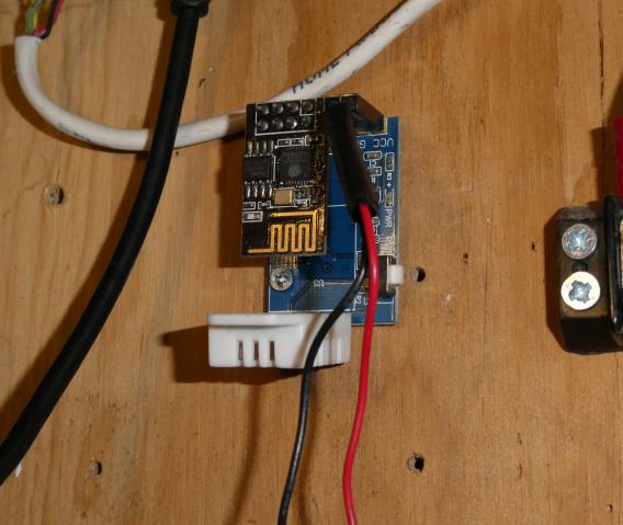
These modules can be found on eBay, Aliexpress and similar listed as DHT22 AM2302 ESP8266 ESP-01/01S Temperature Humidity Sensor WiFi Wireless Module and variations of, with prices ranging from about $1 and up. I had high hopes to use these as temporary or convenient sensors in places where I had not yet run Ethernet or in a location where I know I'd eventually have a permanent sensor at some point, though not quite yet. Except for the fact that these sensors suck. Do not make the same mistake I did and waste time with them because they are not reliable and it's not worth the time and effort to make them reliable. Save your time and money if you want a DIY WiFi temperature/humidity sensor and just manually connect a DHT22 to a D1 Mini or similar ESP8266 dev board.
Like an abusive relationship I spent far more time than I care to admit trying to make these things work, and at times was almost convinced I had them working, only to be disappointed again.
There are two major issues with these boards: 1. The DHT22 sensor stops responding; 2. The readings are inaccurate.
When working, these boards consistently report several degrees high and lower humidity because the DHT22 sensor is heated by the board itself. The onboard 3.3V regulator allows the board to be powered by 5V but because it is a linear regulator, dumps the excess voltage as heat. This slightly heats the board, which then wicks up the DHT22 pins and heats the sensor. Folding the sensor up away from the board helps a little, but the only real solution is to unsolder the sensor from the board and reconnect it through a 6-12" length of cable. While that does solve the sensor heating issue it both ruins the plug-and-play advantage of the board, and also exacerbates the more important issue discussed below. Another option as well is to simply apply an offset to the temperature sensor reading to take out those few extra degrees. Which doesn't quite translate to humidity because the warmer sensor also decreases the humidity reading.
The more important issue, and what really makes these an unreliable waste of time, is the fact the DHT22 sensor periodically stops responding. It might work for a few days, a few weeks, or even a few months, until it suddenly starts giving invalid readings. Or sometimes it works for an hour then stops. Or occasionally fails every day for a week. Perhaps it decides to work for an entire month. Failure, though, is inevitable. Then power cycle the device (not a reset via the "reset" button which only resets the ESP8266) and it begins responding again.Originally I thought this was a problem with my firmware. I had written firmware to allow the device to report its data via SNMP. When the DHT22 sensor stopped responding, the result from the reading would show up readings of "-0.1". So of course I assumed it was my firmware causing the issue which lead to a lot of debugging and rewriting without having a specific cause identified to fix. Several rewrites, multiple DHT22 sensor libraries, and a lot of wasted time there was no solution. This is exacerbated by the lack of an easily accessible serial port for debugging on the ESP-01 module when plugged into the board. Yet, when loaded with Tasmota, the sensor experienced the same problem. With the help of jumper wires soldered directly to the module serial pins I determined that the DHT22 sensor itself was returning a "NaN" reading. Not a Number is the result when the library cannot read from the sensor. And since it was happening with multiple DHT22 sensor libraries under two different firmware, the problem was not one of software.
Knowing that DHTxx sensors require specific timing during communication I then assumed that my wire extensions to move the sensor off the board were causing issues. Even though the DHT22 datasheet specifies a cable length of up to 20M it is possible that stray capacitance, interference or induced currents were messing with communication. It didn't help that the sensor minimum voltage is 3.3V which is the operating voltage of the ESP8266 and thus that of the onboard regulator. I tried shorter extension cables without a measurable improvement. And indeed, even unaltered boards with the sensor directly mounted behaved the same.
At one time I did locate the schematic of these modules on a Github repository. I'm wishing I had saved that information because I can't seem to find it again. However I did confirm there was nothing electrically wrong. The DHT22 sensor power leads were filtered, there was the requisite pullup from the data pin to the power pin, and the data pin was connected directly to GPIO2 on the ESP9266 via the connector.
So what I have is an educated guess that the 3.3V regulators used on these boards is at the ragged edge of its tolerance. The ESP8266 can draw up to about 500mA and while I can't find any real data on the "L3LX" labelled regulators used on these boards (other than they exist) I suspect they are rated for around 150mA based on other 3.3V regulators in a similar package. It looks to me like the undersized regulator leads to voltage drop , which if occurring at the same time the sensor is being read, locks up the sensor.
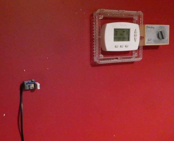
This problem lead to some chaos because I am currently using one of these sensors to provide temperature input to the HA Generic Thermostat controlling my home HVAC. An invalid reading causes the HVAC to either stick on or off with the corresponding ridiculously hot/cold building and the associated wasted energy. I am slowly replacing these unfortunately much longer lived than designed temporary sensors with permanent sensors (DHT22 sensors connected to my 1284 Board).
Temperature And Humidity - DHT22 |
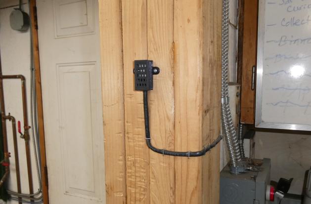
The picture above shows a DHT22 sensor in my shop which is connected by a cable to my 1284 Board which is able to read these sensors from a user configurable GPIO pin. It reports the sensor readings via MQTT at a pre-defined telemetry interval of 1 minute.
I have more or less standardized on the DHT22 temperature and humidity sensor to provide basic climate data to Home Assistant. After trying a number of other sensors including the BME280 and SHT40 I found the DHT22 to provide the most reasonable (notice I didn't say "accurate") readings with minimal self-heating. Self heating was a major issue with the BME280 and SHT40, raising the temperature several degrees and decreasing humidity measurements. Unlike the ESP8266 DHT22 sensor modules above, I have actually had zero issues running DHT22 sensors at 5V on some fairly long cable runs using simple twisted pair CAT5 cable. I typically include the pullup resistor (10K) at the sensor end, and also place two filter capacitors (10uF, 0.1uF) across the sensor power leads.
As I slowly automate each room or area, a DHT22 sensor is typically mounted to provide climate data. And as such they are replacing the (more permanent than I care to admit) temporary ESP8266 DHT22 Modules.
So far when running on my 1284 Board the DHT22s have been very nearly 100% reliable. That "very nearly" isn't 100% so the 1284 Board actually powers the DHT22 from a GPIO controlled source (short runs power directly from an Atmega 1284 GPIO pin, longer runs via transistor with GPIO on base) and if an invalid reading is received, the firmware will perform a power cycle of the sensor to bring it back.
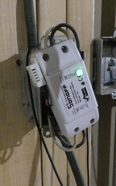
I have also experineced nearly 100% reliabiliy adding these sensors to SONOFFs using short wires soldered to the spare internal header. Tasmota natively supports these sensors. I've started adding them to every SONOFF I flash because it is always advantageous to have temperature/humidity data.
AlarmDecoder AD2USB |
Security/alarm systems can provide a wealth of sensor data to an automation system, not to mention significantly extending that automation system capability by allowing it control of the security system.
My home security system consists of an Honeywell (formerly Ademco) Vista-20P with the standard magnetic and motion sensors. Several keypads and zone expanders allow the system to handle both the house and shop buildings.
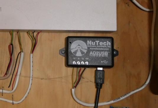
Though there are several projects out there documenting DIY connection to the Ademco ECP bus via Arduino/ESP8266, after weighing the time needed to DIY a solution I ultimately decided to go with the AlarmDecoder AD2USB interface. One of the major deciding factors was that Home Assistant already has an AlarmDecoder integration which fully exposes the capability of the security system.
The AlarmDecoder integration brings out most of the data available from the system as binary sensors. Each zone is a on/off binary sensor indicating whether the zone has been faulted. The magnetic door sensor for the house rear door, for example, is represented as binary_sensor.house_rear_door. Motion sensors are handled the same way. The alarm keypad alarm_control_panel.alarm_panel is also exposed as 13 (at last count) sensor attributes such as (most fairly self explanatory by their names) ac_power, alarm_event_occurred, battery_low. The alarm_control_panel.alarm_panel itself has a state indicating the status of the alarm system (armed_away, armed_home, triggered, etc.). Additionally, there are service calls to set various properties of the panel such as arming and disarming, bypassing zones, and others.
The AD2USB which is connected directly to my VMWare host via USB. The USB port is then passed through to my Home Assistant VM were the integration is configured for serial access over /dev/ttyUSB1.
So far the AlarmDecoder has been 100% reliable. It has never needed a reset, reinstallation nor any maintenance of any kind other than moving the configuration from YAML to UI when HA migrated it. I'm using the binary sensors in several automations, the most useful of which are automatic lights upon entry of areas. I also have notifications for state/attribute changes of the panel such as replace battery, AC power loss, and of course, alarm triggered. Don't want to go into too much detail but a "triggered" state starts a number of automations that have various actions based upon whether I am home or not.
Power Monitoring - CircuitSetup Expandable 6 Channel ESP32 Energy Meter Main Board |
NEED NEW IMAGE
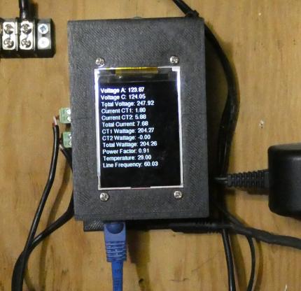
My power monitoring setup is a work in progress right now because my power requirements change along with the potential sources of my power (ie. solar) being variable in the future. At the moment I am monitoring line voltage and current on both phases of my North American style split phase mains feed using a CircuitSetup Expandable 6 Channel ESP32 Energy Meter Main Board. This board is based on two Microchip ATM90E32AS energy monitor ICs which each provide 3 current channels using current transformer sensors and voltage measurement with 16 bit ADC accuracy. The output includes (but is not limited to) raw current, power (active, reactive, apparent), frequency, voltage, temperature, power factor. The 6 Channel Energy Meter Board includes all the support circuitry needed to run the ATM90E32AS including a buck converter power supply so that only one power adapter is required; the board uses it both for power and to take an A/C line voltage measurement. It is designed to directly accept common ESP32 development boards directly via a socket, which also allows up to 6 of these boards to be stacked for a total of 42 current channels.
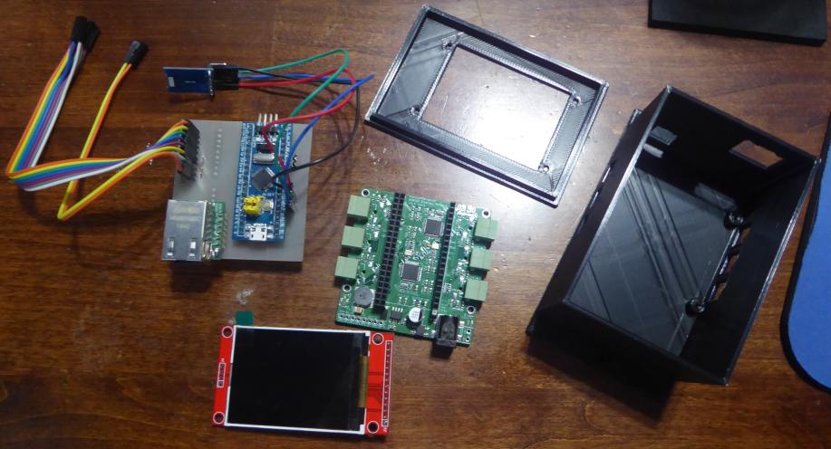
You can probably guess that because this is device screwed to the wall beside the main electrical panel, I did not use a WiFi based ESP32 microcontroller board. Instead, I designed a little "hat" PCB designed to plug into the socket normally used for the ESP32. This plug-in board contains an STM32 "Blue Pill" board, a tiny W5500 Ethernet module, header pins on the underside to plug into the energy monitor board, and headers on the top for serial, I2C breakout (future plans), and SPI/power breakout for a 2.2" ST7735S based SPI TFT screen (not exactly but similar to the linked screen). I chose the STM32 primarily because it was a convenient development board I had around that runs on 3.3V as supplied by the energy monitor board. Additionally at 75MHz, 128K flash and 20K RAM it has enough capability to save energy data to a MySQL database, publish to MQTT, and display on the TFT screen with some pretty graphs.
Unfortunately I was unable to accomplish storing the data to MySQL. I had previously used the excellent MySQL Connector library on Unos and other Atmega based Arduinos, and it does use the Ethernet Stream class exposed by the Arduino Ethernet library so it should work on any compatible MCU under the Arduino framework. I just couldn't get it to work on the STM32. It would freeze up upon connection, or error out with "ERROR: Class requires connected server.". Looking into the library, I couldn't find any reason why it wouldn't work as it was actually a very straightforward library. I opened an issue on the Github repository but we couldn't get to the bottom of it, assuming some library incomputability. So I shelved the idea of recording directly to MySQL for now and instead settled for using MQTT to send the data, abusing the Home Assistant database. Incidentally if you are looking for an example of how to use one of these energy monitor boards to save data to MySQL, I have posted an example on the Home Assistant forum as How To Save Sensor Data To MySQL Database (though using the two channel board connected to an Arduino Uno).
This is a work in progress. Right now I have it monitoring the following: Voltage phase 1 and 2, total voltage, current phase 1 and 2, total current, wattage phase 1 and 2, total wattage, power factor, temperature of monitor board, line frequency. This measurement is taken every 2 seconds and published to published in a JSON encoded MQTT message under the topic "/energymon/energy/" as shown below:
/energymon/energy/ |
Two current channels are in use right now however I intend to expand it in the future to measure the two phases out to my shop, and then the current outputs from two future solar inverters (one per phase). Finally, I'll be using the I2C bus to connect to an ADS1115 analog to digital converter which will take voltage and current readings from the panel side of the solar array.
I do not have a schematic of the energy monitor currently as it is just 3 devices connected directy to the SPI bus (6 channel monitor board, W5500 ethernet, TFT screen). Plus a couple of pin headers, with the SPI bus connection to the 6 channel energy monitor board on the bottom through another set of pin headers. Power comes from the 6 channel energy monitor board via those headers as well.
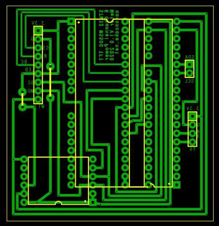
The project was built on a PC board with the same dimensions as the 6 channel energy monitor board.
The PCB is designed using the excellent Robot Room Copper Connection software. Unfortunately, ExpressPCB bought Copper Connection and has renamed it to ExpressPCB Plus, at the same time removing the ability to easily print PCB patterns for toner transfer. This sort of behavior is rather disgusting. Thankfully the old version still works. So if you somehow found a zipped copy of it, it can be manually extracted into the Program Files directory and run without violating the license of the free version.
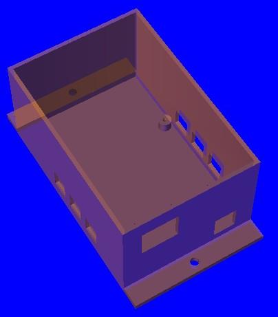
| STM32 CircuitSetup 6 Channel Power Monitor PC Board | STM32 CircuitSetup 6 Channel Power Monitor Case STL Files |
|
|
| Download (.ZIP, 6K) | Download (.ZIP, 63K) |
The Ethernet module used is a tiny WizNet W5500 board for some strange reason often listed on eBay and Aliexpress as USR-ES1 W5500 ENC28J60 module even though it absolutely does not contain an ENC28J60. These modules are very convenient because they plug right into a breadboard and can be easily integrated onto PC boards.
I've said it before and I'll say it again: This is a work in progress. It is about as crude as it can be with a basic functionality level. When powered up, the software initializes communication with the TFT screen, connects to Ethernet with DHCP, the starts communication with the ATM90E32 energy monitor. It then connects to the MQTT broker. Note upon initialization of the ATM90E32 it passes calibration parameters defined earlier. These were determined by comparing energy monitor readings with a multimeter then adjusting until all readings matched. I used a 100W incandescent light bulb as a test load.
Every 2 seconds, a reading is taken from the ATM90E32, a little math performed, then serialized into a JSON string. This is then published to MQTT topic "/energymon/energy/". Additionally the measurement information is dumped to the TFT screen and serial port. I'm just clearing the TFT screen and then issuing tft.print() statements to repaint the whole screen with every measurement. It is ugly, inefficient and slow but at least displays the readings for humans.
As the system is expanded to read the solar panels and additional channels, I will rewrite the display code to be much more efficient and pretty.
This was written in the Arduino environment using the STM32duino core.
Radiation Monitoring - MQTT Geiger Counter |
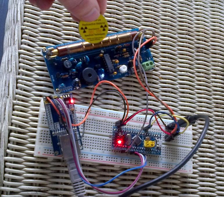
This was a quick project to integrate a RH Electronics Geiger Counter Radiation Detector DIY Kit Arduino Compatible ver. 3.00 into Home Assistant via MQTT. I sort of threw it together on a breadboard because I had all the parts and the breadboard already set up with an STM32 Blue Pill connected to a Wiznet W5500 Ethernet module and there was a topic on the Home Assistant forum discussing Geiger counter integration.
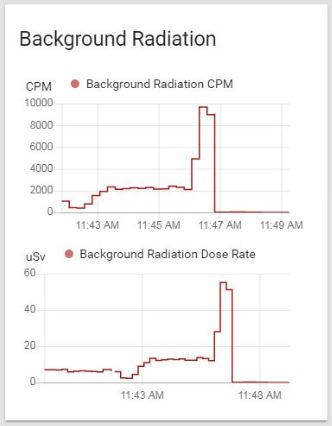
This Geiger counter kit provides a 5V pulse for every beta/gamma particle detection thus making it very easy to interface to virtually anything. I connected the output to STM32 pin PA0 then set up an interrupt handler to increase a count whenever the pin was toggled. Every 15 seconds the count is multiplied by 4 to create a CPM (Counts Per Minute) value. Dose rate is calculated by multiplying the CPM value by a "magic number" conversion factor (this depends on the tube used and can be often found by checking the datasheet, or a bit of Google). This is then published by MQTT on topics /Geiger/cpm/ and /geiger/dose/.
The source code is fairly quick and dirty as this was a bit of an experiment however it ran for several months like this until I needed the breadboard for other tasks. So right now the sensor isn't running. I intend to roll it into an environmental sensor which also tracks particulate matter and other parameters. This code is the example from the RH Electronics website with some MQTT boilerplate added.
MQTT sensors are defined in Home Assistant to receive the values:
mqtt:
  sensor:
############Geiger Counter
    - name: "Background Radiation CPM"
      unit_of_measurement: 'CPM'
      state_topic: "/geiger/cpm/"
    - name: "Background Radiation Dose Rate"
      unit_of_measurement: 'uSv'
      state_topic: "/geiger/dose/"
|
Home Assistant then graphs the sensors which spike nicely when a sample of Cesium 137 is held near the tube.