| Home > My Projects > Home Automation > HVAC |
| Home > My Projects > Home Automation > HVAC |
There are a lot of commercially produced HVAC "smart" thermostats capable of integrating with automation products out there. Examples include the Nest, ecobee, Honeywell, Radio Thermostat and many others. And they all suck! Why do they suck? Say it with me now..."WiFi!". Nothing dumber in the thermostat world to take a device hard wired permanently into a system and force it to connect to the network wirelessly. Guaranteed unreliability, guaranteed obsolescence. And it also occurred to me that with a home automation system, no one actually needs a thermostat.
A thermostat is just something people constantly fiddle with for no reason. Setting the temperature a few degrees higher when they are cold, then back down once they are warmed up. It is usually placed in the most inconvenient position to actually get an average temperature measurement of the building, and quite frankly a single climate measurement of an entire building full of separate rooms and hallways is an obsolete idea anyway.
Therefore I have no thermostats. What I do have are Ethernet connected MQTT commanded controllers which run the house furnace/air conditioner and shop heater. These work in conjunction with the Home Assistant Generic Thermostat integration and temperature sensors to provide virtual thermostats which can be controlled via the Home Assistant UI and automations. Well, I sort of lied in that I do have a thermostat. An old fashioned mechanical thermostat remains connected to the furnace in parallel and is set to 4 degrees. If there was some sort of technological failure and I was unaware for an extended period of time this will maintain a minimal temperature to prevent pipes from freezing.
House - Uno W5100 Ethernet MQTT HVAC Controller |
This was actually meant to be temporary as I had intended to eventually install an Ethernet based commercially produced "smart" thermostat. Except, such a product doesn't exist. And after a short while I found that I didn't actually need a physical thermostat. So the temporary solution became so far permanent and has generally worked very well.
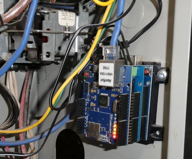
My HVAC controller is simply an Arduino Uno hosting a 4 Relays Shield topped by a W5100 Ethernet Shield. I rarely stack together Arduino shields except in testing, but the convenience of just plugging these boards together was too great to ignore. For a one off temporary item, it didn't seem like a prudent use of time to build something in a non-prototype form.
An A/C capable thermostat is a very simple creature. Typically 4 wires come from a North American furnace (or HVAC unit): common (R - red), heat (W - white), blower (G - green), cooling (Y - yellow or blue). Common carries 24VAC to the thermostat. The thermostat then applies 24V to the correct wire to call the HVAC unit to perform the desired function. Connecting common(R) to heat(W) tells the unit to start the sequence of events that lead to heat (purge vent, turn on igniter, open gas valve, start blower). This operation continues until 24V is withdrawn from the wire. In this way it is trivially easy to control a HVAC unit. Incidentally, you may wonder what happens if you command the unit to produce heat and cooling by applying 24VAC to both the W and Y wires. I can say for certainty that in at least my case, this will start the furnace heating and turn on the A/C unit. As the A/C evaporator coil sits in the plenum directly above the furnace heat exchanger what takes place is a battle of thermal wills. The furnace wins with the result being slightly cooler hot air from the vents. And for that matter, my HVAC unit allows the A/C compressor to be started without turning on the blower fan which is very effective in freezing up the evaporator coil.
There isn't much of a schematic to the controller as it is simply an Arduino Uno stacked with a 4 Relay Shield and Ethernet Shield. The relays connect to the HVAC unit is as follows.
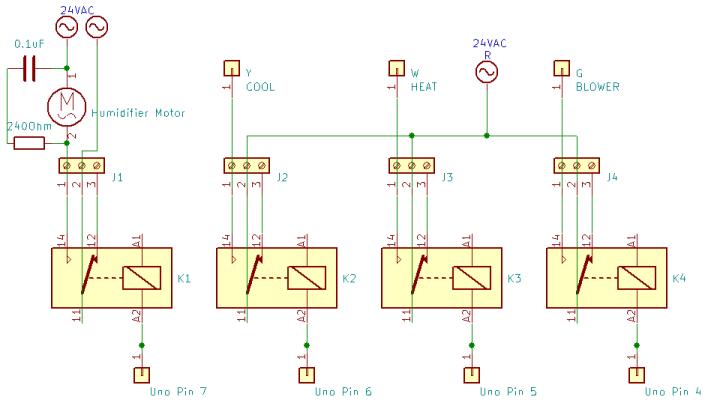
In the schematic I'm representing the relay shield with generic relay symbols, so no, don't expect to grab 4 relays and connect it like this. The important part is how the relay contacts connect. The common (24VAC, R) wire connects to the common terminal of K2 - K4. The normally open contact of K2 connects to the cool(Y) wire, NO on K3 connects heat (W) and finally, blower (G) is connected to NO on K4. K1 is a bit of a special case because it is used to control the humidifier. The humidifier has its own 24VAC transformer so the common-NO contacts of K1 are simply connected in series with the power leads from the transformer to the motor. Note the snubber network made up of the 240 Ohm resistor and 0.1uF capacitor in parallel with the motor. I found the humidifier motor is a nasty little thing which caused major transients when switched off. Bad enough that it was locking up the HVAC controller. I suspect the humidifier motor is a small crude induction motor that was never meant to be switched by anything but a mechanical hygrostat.
The firmware is a fairly straightforward implementation of relay control via MQTT, not much different from what you may have already seen in many other projects. The only real difference is that the code contains some logic to prevent incompatible modes from being set at the same time. For example, if the unit is currently heating and it is commanded to cool without first turning off heat, the controller code will ensure that heat is turned off before switching to cool.
Up at the top some variables are set to define the pins which control the relays for the various functions. Then the MQTT topics for the various modes (heat, cool, blower, humidifier) are defined. The controller listens on these topics to take commands. This is a single purpose device and I'm not very concerned with being memory efficient (not that it would have taken much effort, I just didn't care) so I'm not storing these in PROGMEM or dynamically generating them like I usually do. Matching states are defined in the same way. The controller publishes on these topics to indicate a confirmation it has changed state/responded to a command. DoPublish is used as a flag to determine if the states need to be published and is set true whenever the controller has received a command or otherwise changes state. Then below, my standard uptime/telemetry boilerplate variables used for tracking board uptime, version, etc.
Once the standard Ethernet stuff is set up, note that I define a function PetTheDog(). That function is just a wrapper for the AVR watchdog reset function wdt_reset() which comes from the included library avr/wdt.h. This function is called periodically throughout the code to reset the processor watchdog timer signalling that everything is still working. If there is a lockup event or something which prevents the code from running then after 8 seconds of not being petted the watchdog will reset the processor.
UptimeCounter() is just a clock to track uptime. It is called once per second and increments UptimeSeconds. Once UptimeSeconds hits 60, UptimeMinutes is incremented and UptimeSeconds is reset to 0. UptimeMinutes behaves the same way, incrementing UptimeHours at the 60 mark. And every 24 hours, UptimeDays is increased by 1. Every 60 seconds, the flag SendHeartbeat is set to true which fires off function Heartbeat(). Heartbeat() uses sprintf_P to format the uptime values, FirmwareVersion variable and output of freeMemory() as a JSON string using a formatting string stored in PROGMEM as a template. This string, HeartBeatPublishString is then dumped to the serial port and published on MQTT topic /furnace/tele/.
Starting in setup(), the serial port is started for debugging then the watchdog timer is enabled with an 8 second timeout. It is important for the watchdog to be enabled as early as possible because before the watchdog is enabled, a frozen processor means someone is going to have to press the reset button. The relay control pins are all set to RELAY_OFF before being set as outputs. Setting them with digitalWrite before setting their mode assures the pin is at an expected state first, so to avoid accidentally cycling relays. Ethernet is then started in DHCP mode. If no DHCP address is received within the timeout, then there is no point continuing with execution so the code puts the processor into an infinite loop with a for(;;) (a loop that always evaluates as "true"). Assuming a successful Ethernet link and DHCP address lease, ConnectToMQTTBroker() is called to make the MQTT connection.
ConnectToMQTTBroker contains a loop that runs while .connected() is false, this it will loop continually trying to reconnect to the MQTT broker if the connection is not present. Every time the loop runs, an MQTT connection is attempted with .connect() passing the server name with no authentication. Assuming connect returns a "true" indicating a successful connection, each topic to which the controller will listen is subscribed: BlowerTopic, HeatTopic, etc. Once the subscriptions are complete, PublishStates() is called.
As the name suggests, PublishSates() publishes the current state of the controller to MQTT. It reads each relay control pin (ie. HeatPin) and the publishes a "1" (StateOn) if the relay is on or a "0" (StateOff) if off to the appropriate state topic (ie. HeatState). Storing all these topics and pins in arrays would make publishing states just a loop and a bit more elegant. Meh. Afer all the publishing has taken place, the DoPublish flag is reset to "false" indicating the publishing is done.
Note throughout the code PetTheDog() is called often to reset the watchdog timer. I try to call it just before I anticipate there could be a delay of some kind such as when publishing to MQTT.
Within the main program loop(), the MQTT connection is first checked and if not connected, reconnection is attempted by calling ConnectToMQTTBroker(). If the DoPublish boolean flag is true, then PublishStaes() is called. PubSubClient.loop() is the worker loop for all things MQTT so it must be called as often as possible. It is responsible for processing all MQTT events including generating a callback when data on a subscribed topic is received.
In the event that the controller receives data published on one of the subscribed topics (ie. /furnace/heat/) callback() is called. When an MQTT topic is received via callback a series of if statements use strcmp to compare the received MQTT topic with the topics within the topic variables (ie. HeatTopic). When found, the payload is then checked. If it is a "1" for "on", then the required action is taken. For example, if "/furnace/heat/ = 1" is received, this signifies a request to turn on the heat cycle. The cooling and blower relays are first turned off, a 1 second delay takes place to allow the HVAC unit to react, then the heat relay is turned on to stat the heat cycle. All other topics are treated the same way simply turning off the relays for the other cycles then turning on the necessary relay for the desired function. In this way, the controller does not allow the HVAC unit to be commanded to do something stupid like turning the furnace and A/C on at the same time. Turning on the A/C will always turn the heater off first. If the controller receives a "0" on the MQTT topic, then the relay associated with that function is turned off.
Interesting to note that at in the CoolTopic code block I control both the A/C compressor and the blower. Because my HVAC unit is a furnace with an add-on air conditioner consisting of an exterior compressor/condensor unit and internal evaporator coil in the furnace plenum. So the furnace doesn't know the A/C compressor is operating, won't turn on the blower itself, which will result in a completely frozen evaporator and negligible cool air from the ducts. The humidifier is also simply an independent on/off control as it can run at any time (though I have never seen a need to run one in the summer months while the A/C is operating).
After the relays have been manipulated, the DoPublish flag is set true so that on the next run around the main program loop(), PublishSates is called to publish the current controller state via MQTT.
Each function of the HVAC unit is exposed via MQTT so in Home Assistant each becomes an MQTT Switch. These switches are not designed to be manipulated by human hands (expect perhaps the furnace blower if one wants air circulation) but instead they are controlled via the HA Generic Thermostat. See Climate Control/HVAC for details.
It may be puzzling that this control omits a temperature sensor. Using the HA Generic Thermostat, temperature data is provided by a separate temperature sensor which offers a lot of flexibility.
Shop - Relay Via 1284 Board |
The climate control in the shop currently consists of a Mr. Heater Big Maxx MHU50 50,000 BTU natural gas unit heater. Currently there is no cooling available in the shop but A/C is on the long list of things to do (mini split most likely, or permanently wall mounted window style unit). Therefore, only a single set of relay contacts is needed to switch the R - W connection on the heater. While it does provide a G connection for the blower I can't think of a single reason why independent control of the blower would be needed.
Thus, the heater is controlled via a relay which itself is controlled by the shop 1284 Board. That output is set up as an MQTT Switch which itself is then controlled by a Generic Thermostat. Temperature data is provided by a DHT22 sensor connected to the same board.
Home Assistant Generic Thermostat |
I think it's worth saying a few words about the Home Assistant Generic Thermostat integration since it is the basic control logic of all of my HVAC. The Generic Thermostat integration is undergoing changes as I write this so consider it current as of Home Assistant 2022.11.
The Generic Thermostat is a thermostat implemented in Home Assistant that supports both heating and cooling. It is a simple "bang bang" style thermostat which (when in heat mode) simply activates a switch when temperature falls below the set value (within the hysteresis "cold_tolerance" setting), and turns it off after it has increased above that value (within the "hot_tolerance" setting). It supports an "away" mode with a defined temperature for that mode. For cooling, the operation is the opposite: activate the cooling when temperature is above the set point, deactivate when below.
Unfortunately the Generic Thermostat is very simple and not exactly "smart". It cannot currently support heating and cooling in a single thermostat which means most implementations (mine included) will require two thermostats. And they must be controlled via automations to implement any features beyond simple control. For example, if a "boost mode" is desired to temporarily increase temperature (I don't know why people want this, but it is a common request) an automation must be written to add it. There is also no scheduler built in so this must be automation based as well. Consequently the Generic Thermostat is at the same time very crude, but at the same time infinitely configurable.
Ideally the Generic Thermostat would be a "set it and forget it" configuration. The user should be able to set a temperature, some tolerances, and then the integration would maintain the desired temperature using either heating or cooling as required. This would make a truly useful smart thermostat. At the moment however achieving that behaviour requires a set of trend sensors to determine the season, then automations to enable/disable the appropriate thermostats.
That said, the generic thermostat is a damn handy integration any time you need a closed loop "bang bang" style control. You just have to feed it your value in the form of a temperature (typically using a template sensor to transform the value into a temperature) and give it the switch to control. It could, for example, be used to maintain the liquid level in a tank by being fed the level as a "temperature" and set to control the switch for the pump. Vent fans and particulate level are another example. As long as you can transform the sensor value into a "temperature", you an use the Generic Thermostat to regulate it.