| Home > My Projects > Home Automation > I/O Control |
| Home > My Projects > Home Automation > I/O Control |
The business end of home automation are inputs like a switch toggle, and outputs such as a relay to turn on a light. There are a lot of ways to accomplish this, some very consumer friendly. However the last thing I want are eleventy billion WiFi switches, "smart bulbs" and "smart outlets" at every wall. That's a recipe for disaster and unreliability. That isn't to say I don't use those products yet what it does say, is that they are used when is appropriate for their specific use case.
I needed a board or device which offered inputs for things like switches (or buttons), and outputs that are either relays or to drive relays. The idea being that one of these boards can form "control hubs" that handle a number of switches an outputs. Handling, for example, all the light switches and lights with a room or area. And I wanted the boards to be open hardware with easily available schematics, have programmable firmware that I could replace if I wanted to, speak MQTT, connect via Ethernet, and offer properly isolated inputs (preferably optical). Such a board or device, I could not find at the time. I did find several that ticked a few of those boxes but none that ticked them all. There are a number of "Arduino PLCs" and "Industrial Arduinos" available which I was very keen on until I actually tried to buy some. Many were out of stock, some shipped from the other side of the world at insanely inflated prices, and unfortunately all gave the impression that if I wanted to use them, I better buy a 100 year supply because there's no certainty of future availability.
And I kind of already knew from the start I wanted to build my own hardware.
I have designed two I/O boards which I use as control hubs for rooms or areas. The first based on an Arduino Nano and W5500 Ethernet module which I refer to as "The Nano Board". The second based on an Atmel1284 and W5100 Ethernet I refer to this as the "1284 Board". Both provide optically isolated inputs and non-isolated outputs with the 1284 Board also designed with extra I/O among other things.
The Nano Board |
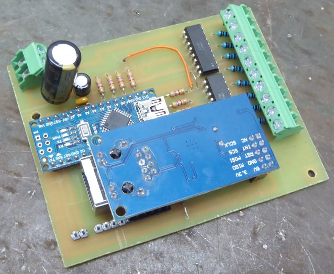
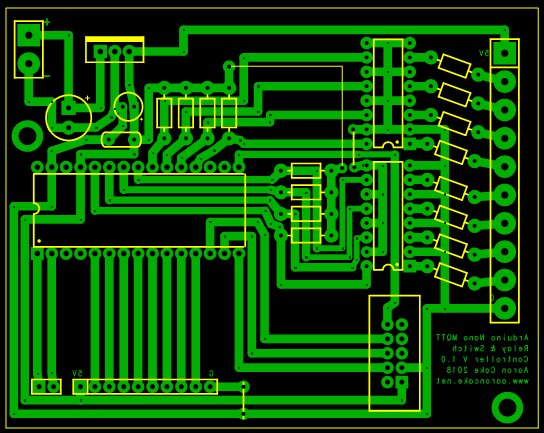
This was my first I/O board design with the goal of providing stable status of 8 inputs, and control of 8 outputs via MQTT over Ethernet. The board consists of an Arduino Nano, W5500 Ethernet module, power supply using LM7805 linear regulator, and two LT847 four channel opto-isolators. The circuit is fairly simple. Nano pins D2 - D9 are broken out to the pin headers you see below the Ethernet card, designed to drive relay modules. D0-D1 (TX, RX) are also broken out to a two pin header so the serial port can be accessed and as two "extra" I/O pins if needed. Analog pins A0 - A7 connect to the outputs of the 8 opto-isolators via pullups. And the input of each opto-isolator have a 220Ohm series resistor as they assume a 5V input (additional series resistor added externally as required).
When I first designed this board it was simple enough that I didn't create a schematic and just went straight to PCB design. So I've retroactively created a schematic if you wish to reproduce. Just note that the opto-isolators might not match up to the same Nano and screw terminal pins on the schematic vs. the PC board.
The PC board was designed to be as reasonably compact as possible with the idea it should fit within a metal 2 gang North American electrical box. It just barely does so theoretically it could be retrofitted. Through a minimum 3 gang would probably be required in order to fit the necessary relays.
The PCB is designed using the excellent Robot Room Copper Connection software. Unfortunately, ExpressPCB bought Copper Connection and has renamed it to ExpressPCB Plus, at the same time removing the ability to easily print PCB patterns for toner transfer. This sort of behavior is rather disgusting. Thankfully the old version still works. So if you somehow found a zipped copy of it, it can be manually extracted into the Program Files directory and run without violating the license of the free version.
| Nano W5500 Board PCB |
|
| Download (.ZIP, 9K) |
I manually etched the boards in ferric chloride using the toner transfer method to add the resist layer. Then drilled all holes on the drill press. As this is just a single layer board I didn't feel the need to have it produced.
The firmware, written in Arduino, will be covered a bit later after I've shown the boards which run it. See the firmware section.
The primary purpose of this board is to control a number of on/off devices (such as a non-dimmable light), and take inputs from on/off human controls (such as a light switch or button).
Here's an example of the board set up on the bench for testing. It is powered by a small mains to 5V power supply.
Two quad relay modules are connected to the "relay outputs" header (D2 - D9 pins). It is connected to Ethernet, and the USB cable attached for debugging to a serial console as it is being tested and integrated into Home Assistant.
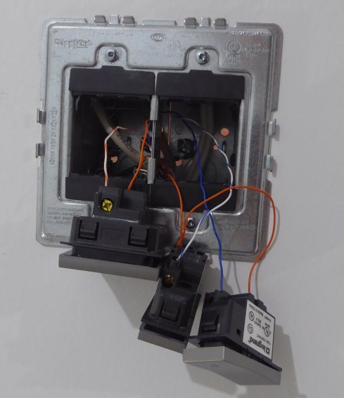
Here's an in-progress example of installing this board in my shop to control the 6 lights and take input from 6 buttons. I often use the shop as a testing ground since the wiring is external so it makes accessing the I/O board (for programming) very easy and everything is just mounted to the wall near the door.
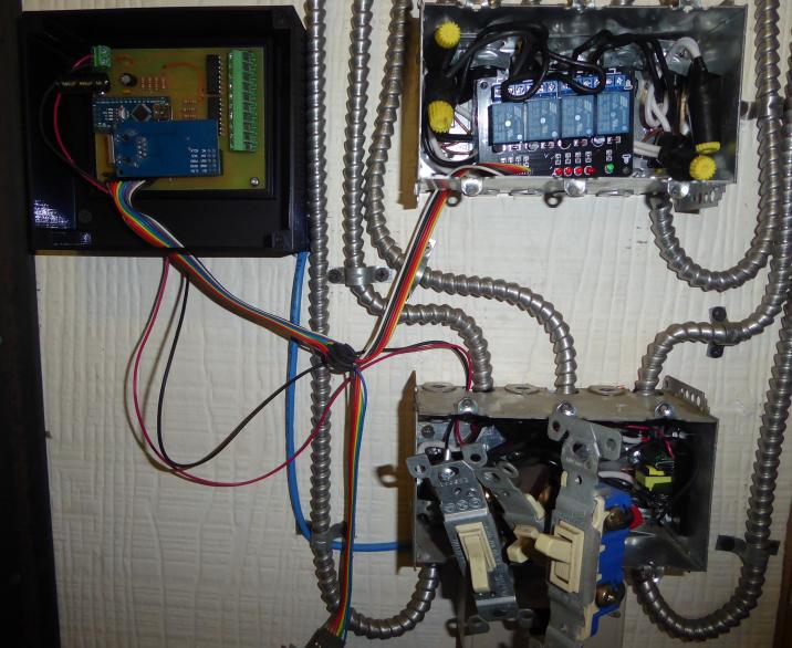
This installation is a retrofit, replacing the standard light switches I installed when I rewired the shop. In the top box, you can see that the switches have been replaced by a 4 relay module while the bottom box is awaiting its relays.
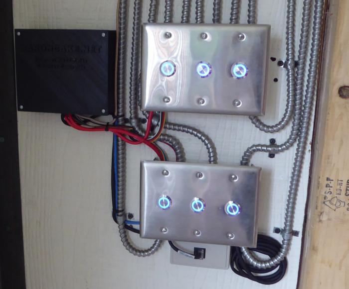
I chose to use illuminated buttons as inputs primarily because with buttons it is easy to implement multiple functions with one input. For example, different durations of presses could activate different functions. The buttons were mounted into stainless blank plates and simply connected to 5V on one side of the contacts, then the other side of each contact to each opto-isolated input on the board.
MQTT topics control the relay outputs, and an MQTT topic is published when a button is activated. The details of this will be covered later when I present the software.
The Nano board is highly reliable and to this day, not a single one has failed, disconnected from the network or otherwise not performed as designed. Typical uptime on the boards was dictated simply as the time between power outages. However, the Atmega328 on the Arduino Nano started to become a limitation. While fine for basic I/O use, the Nano has only 2K of RAM which really limits the amount of "other" tasks I can perform. It makes OTA software updates impossible, and both RAM and flash space start to go away very quickly when libraries for other functions such as sensors are added. My board design left only two usable extra outputs, D0 - D1 (the UART) when used, preclude the ability to run the UART. This of course got the brain working and I was thinking of features I would want in a "new" board: more I/O, spare I/O, more RAM & flash, expansion capability, single board, PoE, OTA, status indication, and other features. So, I designed a new board with those goals in mind.
The 1284 Board |
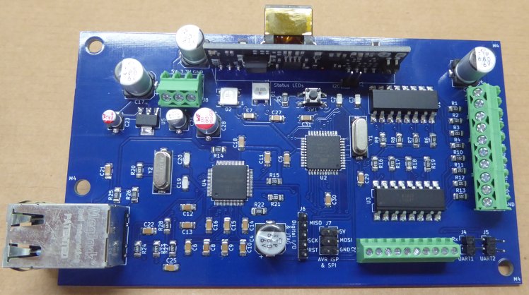
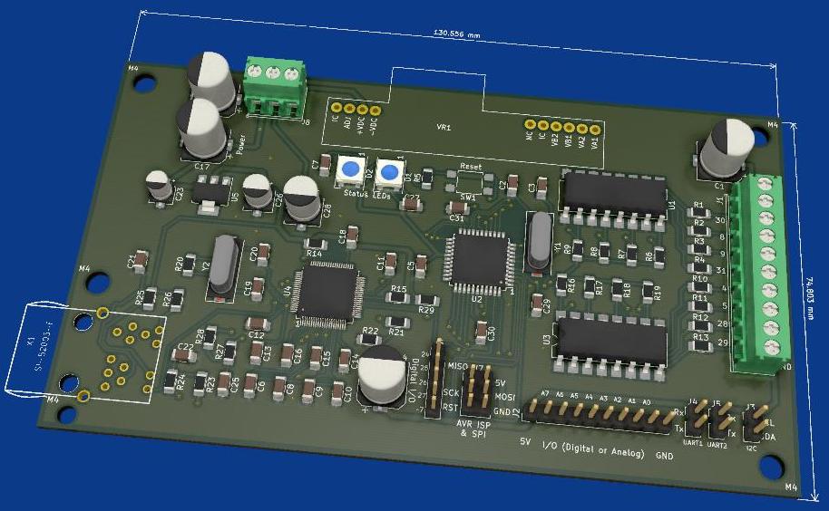
The 1284 Board is, unsurprisingly, based on the Atmega1284 microcontroller. It is designed from scratch for the purpose on a 2 layer PCB. Incidentally, this was the first project I had ever tackled with KiCad, the first PC board I have had fabricated, and my first SMD project! As such the layout of the board isn't as optimal and compact as it could be.
The 1284 Board has the following specs:
I chose the Atmega1284 for several reasons. First, it had the I/O and memory I required while not being excessive (as in the Atmega2560 used on the Arduino Mega). Second, it is well supported in the Arduino framework using MightyCore (I am using the "Bobduino" pinout) assuring a broad compatibility with libraries supported in Arduino.
The input opto-isolators are configured in the same way as the Nano board. However unlike the Nano board I chose to use the analog capable pins in the "output" header which will allow for attachment of 0-5V analog sources (such as a thermistor, pressure sensor, potentiometer). Since the Atmega1284 has plenty of I/O I also broke out the I2C bus and two UARTs to headers. As well, the 6 "spare" pins I ended up with became J6, my "spare" I/O header which is intended to attach sensors (such as DHT) or other devices. The SPI bus is broken out to the AVR ICSP connector J7 which allows the board to speak to SPI devices (such as screens).
Incidentally choosing the W5100 Ethernet controller was a mistake. I had assumed that the Ethernet modules used on my Nano board were W5100 based, so continued on with that chip in my new design. Turns out that they are in fact W5500 devices. The W5500 is actually a much better part: smaller, fewer pins (ditches the parallel bus), less power use, much less heat (W5100s run hot), more sockets, more memory and still in production. Has the W5100 created me any problems? No, nothing besides the higher price and bigger package.
The Silvertel Ag9700-2BR PoE module is an easy to use 5V output IEEE 802.3af PoE module that includes everything needed to build a PoE capable device. I chose the SI-52003-F MagJack RJ45 connector as it was easily available and PoE compatible (includes the taps for the 4 power lines). Only disadvantage of the SI-52003-F is that it is not the cheapest option at about $8 each.
Version 1.0 of the 1284 board forgot a pullup on the W5100 CS line. While that didn't effect operation (SPI library sets the internal pullup for the CS pin) it did mean that programming the 1284 via the ICSP header once the W5100 was installed became a bit problematic. Oops. Therefore I had to remember to load the 1284 with firmware that made sure the W5100 was not active on the SPI bus. The Arduino "DHCP Printer" example worked well. Or just not programming via SPI so by loading the Arduino boot loader, I could instead just use the UART after manually tapping the reset button at the right time. Another option is to manually hold the W5100 in reset with a jumper. So version 1.1 added the pullup and also made a few layout changes on the board. If I have to do another board run, version 1.2 will also tie the W5100 reset line into a processor pin instead of just pulling it high. Would be nice to be able to hard reset the W5100 by software, even though I have never found that necessary.
| KiCad Project |
|
| Download (.ZIP, 141K) |
You can download the KiCad project files for this board above. I've included the necessary libraries so you'll need to add them to KiCad.
Here's an example of this board used in my bathroom. The board is installed in the room automation cabinet and currently runs all the main peripherals in the room such as switches, lights, and vent fan.
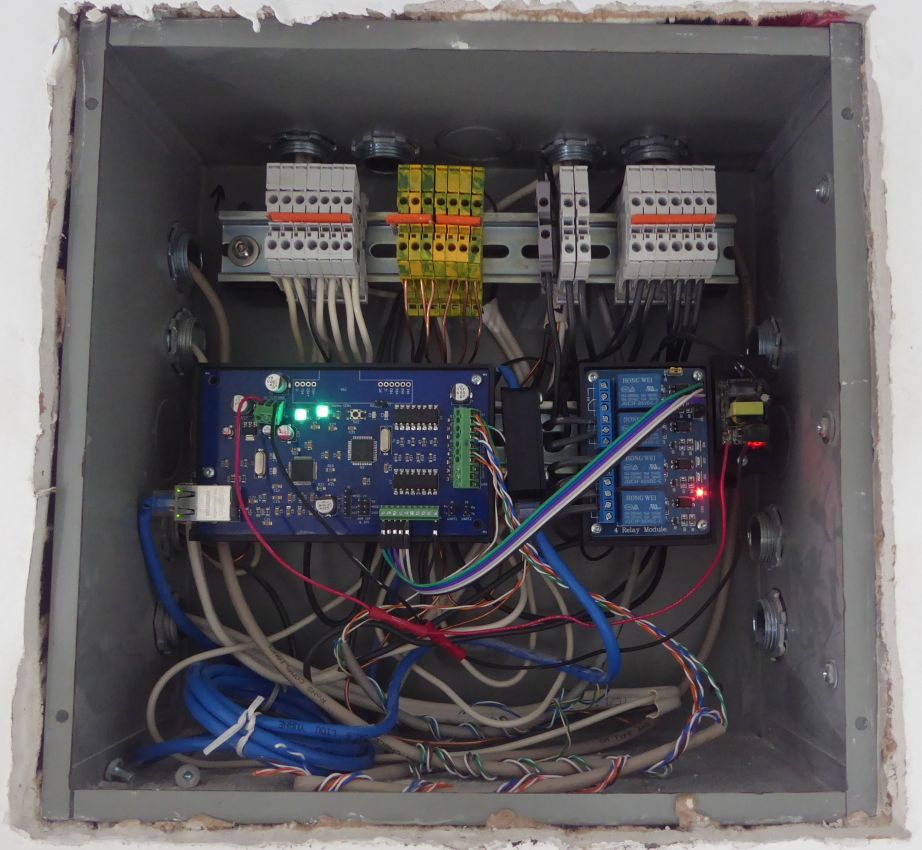
Yes, that wiring is brutally messy however the picture was taken in-progress just after the switches were wired before things had been tied up and neatened.
In this example, the board is using external power from a small 5V power supply to the right. 4 relays are mounted and control the room lighting and the vent/extractor fan. All the switches in the room are connected via CAT5 to the opto-isolated inputs using low voltage (5V) signals. Incidentally, this makes bathroom switches intrinsically safe to operate with wet hands. These are Legrand adorne switches in "Magnesium" with stainless plates. My wallet is still angry.
Functions based on "press" time are possible with switches by simply toggling the switch, waiting the time period, then toggling again. Though not very user friendly and could be prone to false triggering.
1284 Board I/O Expansion |
It wasn't long before 16 I/O channels (8 dedicated to inputs) of the 1284 Board became a limitation. Primarily on the input side because once you have the freedom for a lot of user controls, you tend to place them in convenient spots.
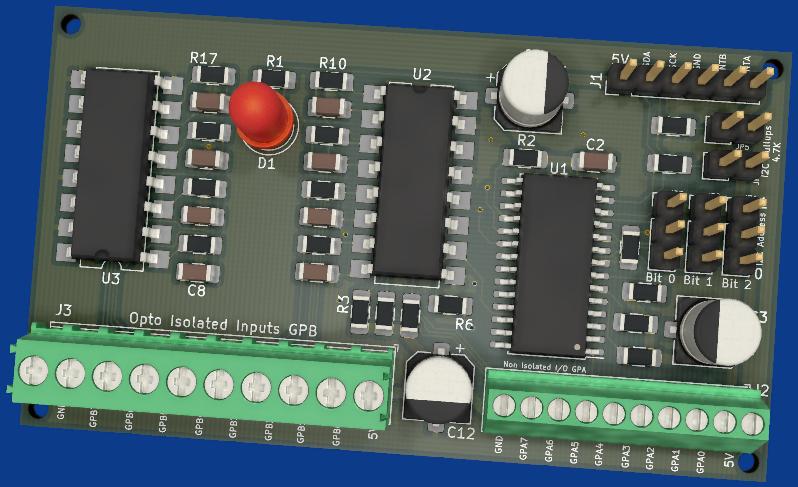
The 1284 Board breaks out the SPI and I2C busses to headers so I designed I/O expanders to connect to the I2C bus.
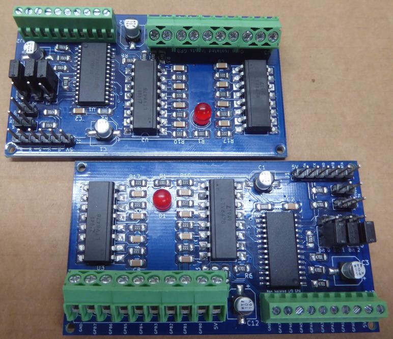
These boards use the popular MCP23017 I2C I/O Expander to provide 16 additional I/O channels. 8 are broken out directly designed for interfacing to relay modules or similar items needing a logic level control (5V). The remaining 8 channels are connected to opto-isolators (as on the 1284 / Nano Boards) to provide dedicated input capability. The I2C address is selectable via a set of 3 jumpers which means that up to 8 of these boards can be used to expand the 1284 Board to a further 128 more I/O channels. The board also has jumper selectable I2C pullups (4.7K) and also breaks out the MCP23017 interrupt pins to headers.
You'll see the familiar LTV-847s quad opto-isolator used for the input section (GPB) pins while the GPA pins are broken out to a terminal strip directly. There isn't much to using the MCP23017 on the basic level and there is an excellent Arduino MCP23017 library which implements the standard pinMode(), digitalRead() and digitalWrite() functions.
| KiCad Project |
|
| Download (.ZIP, 54K) |
You can download the KiCad project files for this board above.
I'd like to say I planned for the width of this board to be almost exactly that of the height of the 1284 Board, but it was a happy coincidence. And it allows easy rapid prototyping of a holder for both boards.
Nano And 1284 Boards Firmware |
One of the reasons for building this board, beyond needing what I couldn't find already produced, was to provide a project to learn and practice my C++ skills. I just wanted to preface before presenting the current code because it does show some fairly dodgy code structure such as copy-paste duplication sections (to build the MQTT topic strings). It is due for some refactoring.
I did most of the development using Microsoft Visual Studio running the excellent Visual Micro extension which allows development within the Arduino framework.
The firmware version 3.50 is the latest production version and presented below. It provides the following features:
The firmware version above is the current production version, deployed across my Nano and 1284 Boards. Note that support for the MCP23017 board is not yet implimented. Haven't needed it yet even though I expect to in the future.
Libraries used in the code are shown in the introductory comments. If compiling for the Atmega1284 then the MightyCore Arduino core is used with the pin configuration set to the "Bobduino" pin mapping.
At the top you will see the "CONFIGURATION DEFINES / VARIABLES" section. That is the master configuration section for the code and how each board is configured for its desired location/use and with any extra sensors. In "SET BOARD LOCATION" I #DEFINE the name of the board I am compiling for. The idea being that the pre-processor then uses that define to make decisions lower on to configure the compilation for the board.
For example, above it shows #DEFINE TST1284BRD so I've told the pre-processor I want to compile for my test board. A few lines down, the #ifdef statement tells the pre-processor that if I have defined TST1284BRD, to also define some DHT22 sensor info, which will later on be used to enable the DHT22 sensor support on the defined pins and turn on RFID reader support. Later on the defined board is used to set the set things like the Ethernet MAC address and name of the board for MQTT topics. Slowly with each version I'm moving more and more configuration into that section with the goal that when configuring a new board, nothing "lower" than that config section should need to be touched.
I'm not going to go line by line to explain the code however here's a quick rundown of how it works. I feel like it is reasonably well commented.
When the board is powered up it first enables the 8 second watchdog timer then loops through the designated output pins in array RelayPins[] and then sets them all to RELAY_OFF (defined as HIGH, because most but not all relay boards are active LOW). This prevents the relays from sequentially activating when the pinMode() is set. The InputPins[] array is read through as well to store the state of each input so that the board will know if the state of a pin has changed later on as it scans through them. It then starts the Ethernet and waits for a DHCP address. If no address is received, the processor goes into an infinite loop so the watchdog timer resets it after 8 seconds. This is a recovery method in case the board is powered up without a network or DHCP server. Something that could happen for example if the house has just recovered from a power outage. Assuming Ethernet has started up an address received, it performs any startup or initialization tasks which might be needed for any enabled sensors. Finally, it attempts to connect to the MQTT server specified in MQTTServer[].
The firmware loops while MQTT is not connected, continually trying to connect. Prior to attempting an MQTT connection the 2nd WS2818B status LED is set to orange. During each loop, the MQTT topic for the Last Will and Testament is built by using sprintf_P to copy BoardTopic and LWTTopic (out of PROGMEM) into variable BuiltTopic formatted by template LWTTopicTemplate to end up with /boardname/lwt/ . This is a method I use throughout this code to save memory by dynamically generating MQTT topics and payloads rather than storing them in RAM. The MQTT connection uses no authentication. Assuming MQTT connects, the status LED is turned green and then "online" is published to the LWT topic. On each MQTT connection attempt, MQTTConnectionAttempts is incremented by 1.
Once MQTT connects the board then subscribes to the topics /boardname/r(number)/ where (number) is the index of RelayPins[]. For example /boardname/r0, /boardname/r1, and so forth. The topics are generated on the fly instead of being stored in an array to both save a lot of memory, and to allow an arbitrary number of I/O pins to be defined earlier in the code.
If MQTT does not connect, then the status LED is turned red and the board hard delays for 3 seconds before trying again. If MQTT has not connected for the numbers of attempts specified by MQTT_MAX_CONNECTION_ATTEMPTS then Reboot() is called to use the watchdog timer to reboot the board.
Once all the setup has taken place, the board enters its main loop(). Within the loop ArduinoOTA.poll() is called every cycle to allow the OTA library to process events and begin an other-the-air firmware upgrade if one is pushed. OTA is only used on the 1284 Board due to memory constraints on the Nano so a compiler directive only includes OTA if compiled for the Atmega 1284. The MQTT connection is checked and reconnected if necessary. The loop will be stalled if MQTT is not connected as ConnectToMQTTBroker() will run a blocking loop. And MQTTClient.loop() needs to be called as often as possible so the library can process MQTT messages/callbacks from the Ethernet buffer and maintain the connection.
Various timers are used in loop() to run events at scheduled intervals. Every second, the UptimeCounter() is called which just increments an uptime counter of seconds, minutes and hours to keep track of board uptime. In that function, every minute count, Heartbeat() is called which publishes an MQTT message on /boardname/tele/ that contains a JSON string of uptime, IP address, free memory, and the CPU model of the board.
If there are sensors enabled (such as DHT22) then every SensorInterval (60 seconds) readings are taken from the sensors and published into the MQTT topic /boardname/sensor/ as a JSON string containing the sensor name and value(s). The "sensor framework" is designed to be expandable. The idea being that the sensor specific code just needs to be added here to support more sensors.
And the DHT22 is a special case because it just sucks so hard. As a temperature/humidity sensor they are reasonably accurate and not subject to self-heating. But they can be very unstable. I have found that no matter how well shielded or filtered, at some point a DHT22 will hard lock and stop returning a value. The only remedy is a power cycle. Therefore, the DHT22 sensor code contains logic to detect a failed DHT22 sensor. If DHT22_POWER_PIN has been defined it means that the DHT22 sensor power supply is connected to a processor pin that can be controlled. In the event of a failure, the DHT22 library returns "NaN" so that is detected and a flag DHT22ResetNeeded is set to "true". Next time around the loop the pin defined by DHT22_POWER_PIN is set to LOW, turning off the DHT22. After DHT22ResetInterval (2 seconds) the DHT22_POWER_PIN is toggled back to high . This completes an automatic reset of the sensor. If DHT22_POWER_PIN is not defined then the processor has no way to reset the sensor so on a NaN condition from the library, fallback values of of 99.9 (temperature) and 199.9 (humidity) are assigned.
Of course the most important function of these boards are to take inputs and communicate that via MQTT to Home Assistant, and take MQTT commands and control devices. Every InputCheckInterval (100 mS), the SwitchPins[] array is looped through and every input it checked and compared to its previous state stored in the LastInputState[] array. If it is different, it means that an input state change has occurred. The code doesn't care what that state change is, whether it be high or low in the sense that it is only looking for a change from the last known value. The value InputHoldCount[] is increased by 1 to count the number of InputCheckInterval cycles the input value has changed over. By doing this, it is possible to determine "hold" time for things like buttons. To get a real number in mS, the hold count is multiplied by the interval and stored in InputHoldTime. Inputs like switches could cause this to just keep counting forever and return a ridiculously high and useless hold time when they are next toggled so a MaxInputHoldTime is defined and if the hold time greater, the hold is ignored and the new state assigned to LastInputState[]. If the input has been freshly changed (ie. on the first cycle noticing the change) the state of the input is published via MQTT to \boardname\s(position in array).
The loop has continued to count the number of intervals the input is held for. When then input changes again, two values are published via MQTT. First, the state of the input as either a 1 or 0 is published as above. Then the InputHoldTime is published as /boardname/s(position in array)/held/ to supply the hold time of the input in mS. Since the push/hold event has completed the InputHoldCounts[] for that position in the array is zeroed out, ready for the next state change. See that I'm only publishing these events via MQTT; the board itself makes no decisions based on inputs and does not change any outputs.
Also in the loop, the RDM6300 RFID reader (if enabled by compiler directives in the Configuration section) is checked for a scanned tag. The reader is simply connected to the serial port RX line which is checked for waiting bytes. Then those bytes are read and processed into a valid RFID tag ID (if there is a valid checksum, etc.) which is converted to cstring, then published to MQTT topic /boardname/sensor/ as a JSON string like {"RDM6300":"tag id"}. The RFID code was borrowed from from the Arduino RDM6300 library and modified to work directly with the hardware serial port instead of the Stream class due to issues I experienced getting it to work with the hardware serial (the library seems to be designed for SoftwareSerial).
At every MQTTClient.loop(), PubSubClient checks for published messages to subscribed topics. When the board receives an MQTT message, MQTTCallback is called to process it. You'll see the familiar copy-paste code to loop through the RelayPins[] array and then dynamically generate the topic names in the format of /boardname/r(position in array)/ . It then compares the generated topic with the topic on which the MQTT message arrived. If they don't match, it moves on, generates the next topic with next position in the array, and makes the comparison again. Now if it does match, the board looks at the received message. If the message is "1" to represent "On", it sets the corresponding pin stored in RelayPins[current position in array] to the value of RELAY_ON. Which confusingly, is usually a digital LOW because most if not all of the common opto-isolated relay board modules are actually active LOW, and inactive HIGH. Consequently if the MQTT message is "0" for "Off", the pin is set to RELAY_OFF (probably HIGH).
You can see in the comments at the top that I keep a running list of changes I'd like to make including new features, fixes and ways to improve the code. As being the legacy of one of my first C++ projects there is a lot of refactoring that needs to happen. I'm going to move the topic generation code into a function. The pin state scanning will also move into its own function primarily to facilitate the addition of pins on the MCP23017 expansion boards. There are a number of duplicate cstring variables which can be all consolidated into a re-usable universal buffer. The publishing of MQTT state topics needs to be moved out of the MQTT callback function as PubSubClient documentation specifically warns against publishing within a callback.