| Home > My Projects > Home Automation > Architecture and Application |
| Home > My Projects > Home Automation > Architecture and Application |
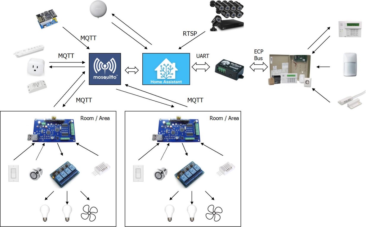
As I have alluded to, the architecture of my system for the most part follows a controller-node-device paradigm. Home Assistant serves as the central controller to which all information is fed, and from which all commands are issued. Each node is a room or logical area of the house which may consist of one or more controllers. Devices (which translate to Home Assistant "entities") are then within those nodes and may be controlled by a controller or function as their own controller (ie. a standalone sensor).
The the high level overview of basic architecture is represented in the diagram below without referring to any specific area of the house.
Home Assistant and MQTT Servers |
Home Assistant sits at the center of the system functioning as the central hub to which all data is fed and all decisions are made. As detailed in Protocols and Standards nearly all communication to Home Assistant takes place via MQTT which is handled by the Mosquitto MQTT Broker. Home Assistant maintains a continuous connection to the MQTT broker (running locally on the same virtual machine as Home Assistant) and subscribes to the appropriate topics (those defined as entities, sensors, etc. in HA configuration).
Alarm/Security Panel |
Home Assistant also directly communicates with the AlarmDecoder via USB UART to communicate with the alarm panel. The alarm panel provides data from all its sensors (represented in HA as entities) while also taking commands (ie. set "Arm Away"). This is accomplished by the HA Alarm Decoder integration.
Google Homes |
Google Assistant integrates with Home Assistant via the HTTP API. It is sort of an interesting case in itself since Google Home voice requests, such as "Hey Google, turn on the living room lights" must pass to Google's servers in the "cloud", which then processes the request and makes an API call to Home Assistant with the result. The Google Home can also function as a media player under which Home Assistant make an HTTP request to the Google Home device directly, supplying the URL of the media to play (as well as other parameters). As such it is both reliant on Google's 3rd party services and also directly accessible.
Surveillance Cameras |
Surveillance cameras integrate to the Home Assistant camera integration and are accessed via RTSP streaming. The only uses for the camera stream are to provide convenient remote viewing via the HA front end and take snapshots/recordings for certain automations. My camera system does not support any sort of API for remote management and I do not use cameras as motion detection sensors due to the high CPU use for this method compared to just passive infrared or break beam motion sensors.
Rooms and Areas |
Each room or area of the house is a "node" which is primarily controlled by one or more I/O controllers. These controllers receives user inputs from devices like light switches, buttons and any other on/off contact type devices (motion sensor, door contact, etc.). For example, a user walks into a room and (assuming the automation has not already reacted) clicks a light switch. This switch sends a low voltage signal to the I/O board, which then sends an MQTT message. Home Assistant reacts to that MQTT message by firing an automation. That automation turns on a light, which sends an MQTT message to the I/O board that then switches the appropriate relay. The I/O boards are typically used for any permanent fixture that is "wired into" the house. Switches, lights, ventilation fans and other fixtures that either generate a simple on/off signal, or require simple on/off switching.
Each room of the house is slowly being gutted and renovated. At that time, it is being rebuilt with automation and future access to the electrical system as a primary goal. What does this mean? It means conduit, conduit and more conduit. As much as we would like to think we can see the future and anticipate all future needs, that just isn't possible. So the only way to future proof appropriately is to make sure that the system can be changed to meet future needs. To run more wires to a switch box for an additional switch or sensor, for example . To run another wire to a light box if a fixture is changed to a ceiling fan or multi-bulb luminaire. Or deity forbid, to remove all the automation and convert the electrical system back to standard. The only way to accomplish this without having to rip into walls is through use of conduit.

In each room or area, all conduits then lead to an electrical box that is embedded at an appropriate point. The image above is an example of some of the conduit leading to switch boxes in my bathroom. All of that conduit leads down into the crawl space, and up into an electrical box which is mounted in the wall adjoining the attic space near the top of the vaulted ceiling. This location was chosen as it is symmetric with an exhaust fan on the same wall making the box easy to access, and easy to hide with another fan grill. the spot also provides an ideal full room view for an unobtrusive PIR motion sensor.

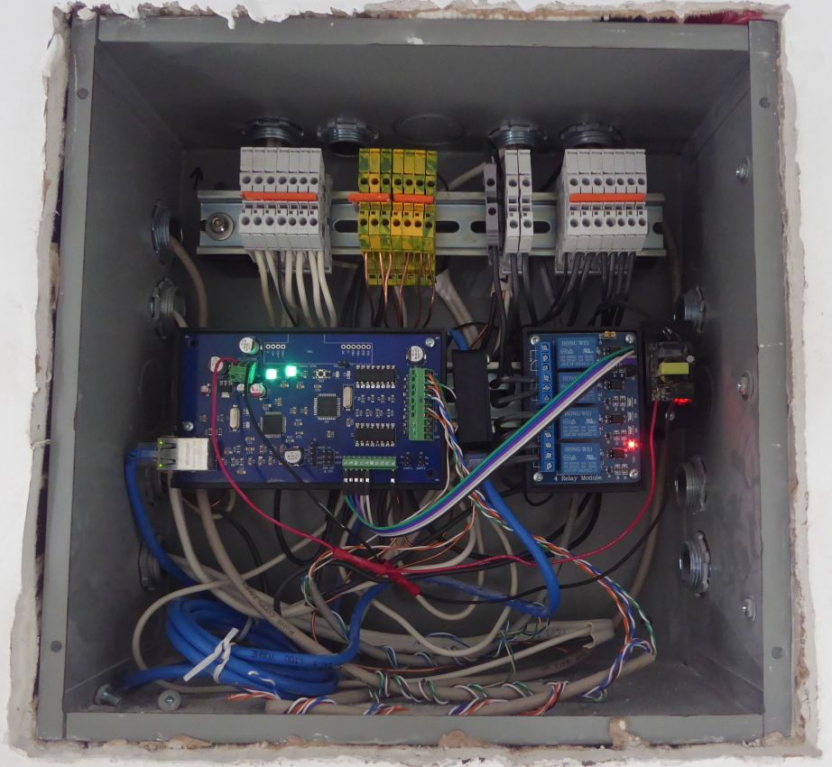
Sometimes this box is placed in another location. For example, the conduits in my bedroom all lead through the floor into the basement, making between the floor joists in the basement under the bedroom a convenient location for the control box. An open basement ceiling makes conduit runs all the way to the box unnecessary.

The board shown in this picture receives power via PoE. One aspect of powering via PoE is that the control equipment continues to operate during power outages as the PoE supplying switch is fed by a UPS. The advantage of this is negligible at best considering the appliances it controls wouldn't have power in this scenario.
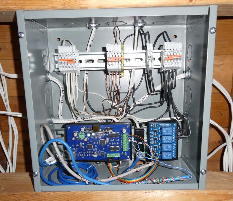
Within the electrical control box lives as much of the automation hardware as possible for the room / area. Typically this means the I/O board and relays plus all of the electrical connections needed for the room / area circuits mounted on DIN rails. Sticking with the bathroom example, here's the bathroom box all kitted out with a 1284 Board, a small 120V to 5V switching supply to power it, and a 4 relay module which then switches the lights and exhaust fan.
Outputs to drive relays are on located bottom right on the control board and connect to relay modules via short cables. Inputs from user controls or on/off (contact sensors) connect to the terminal strip on the right side of the board. Notice that the interior of this box is powered by a small 5V power supply located to the far right.
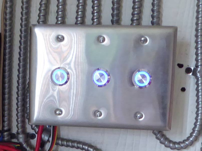
The aforementioned user inputs are typically light switches or buttons. Going with this approach means that I have my choice implement the controls which best suite the room or purpose. For example, in the bathroom I use Legrand adorne switches in "Magnesium" finish with stainless steel plates.

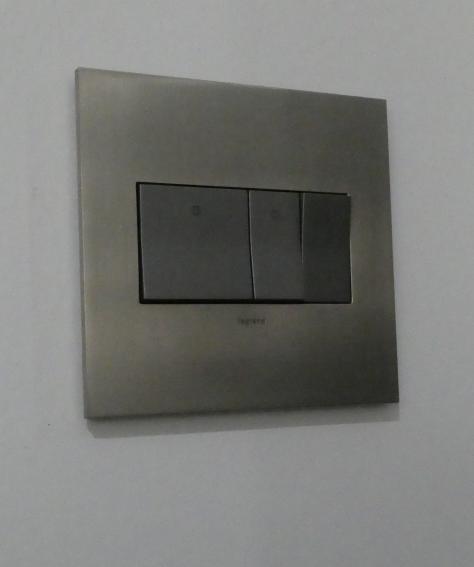
Each switch wires between 5V and one of the I/O board inputs and as such changes input state when togged on or off.
Another example in my bedroom, using grey decora style switches to match the room aesthetic.
Low voltage switch wiring is great because it allows a lot of freedom with inputs. All kinds of whacky and fun things can be used safely for switches. Like old elevator controls, a jumper cable and nail, antique knife swithes, big red industrial "STOP" buttons. Frankly anything that can make or break contacts reliable. I have a uranium glass display cabinet with UV lights already switches by a large copper antique knife switch. That will be fun to integrate into the automation
Switches and Buttons |

In my opinion, providing a familiar interface for manual control is absolutely key in any home automation system. There are a lot of fancy "smart" switches out there. And most of them are terrible if not for the primary reason that they are Wi-Fi based. Many of them provide no physical feedback that an action has been achieved because they are touch sensor based. Having used these things before I find myself frustrated because locating the area to touch now becomes a visual exercise not an instinctual tactile one. Touch the magic spot and nothing happens. Is that because there is a delay? Or because I missed the one square inch area required to activate the thing? This problem goes away with a real switch (or button, or slider) because the user is rewarded with an immediate tactile feedback and change of state. So even if there is a slight delay (as we have all experienced when turning on certain types of lights such as fluorescent) there is no question something happened or will very shortly happen. Switches don't require instruction, typically.
Importantly, remember that these human interface elements do not perform an action such as switching a light by themselves. They simply send a signal to the I/O board, which then publishes an MQTT message (or multiple messages). Home Assistant responds to that MQTT message by performing an action. In the case of a light switch, this action is to turn on a light entity (typically via publishing an MQTT message back to the same I/O board, though not necessarily).
Sticking with the light switch example, if a switch is toggled then the I/O board will publish an MQTT message representing that switch change of state. If the switch is turned "on" the MQTT message will be:
/bthrm/s5/ = 1
In this case, the bathroom (bthrm, because characters are expensive) board sent a message saying that input ("switch" or s) 5 was toggled "on" (1). As you can probably guess, if the switch is toggled to "off" then the message would look like:
/bthrm/s5/ = 0
"On" and "off" are quite deliberately quoted because in most cases, the actual physical state of the input doesn't really matter. Which sounds counterintuitive until you see that Home Assistant acts on that message by triggering an automation to toggle the Bathroom Ceiling Light:
#############BATHROOM SWITCHES
######BATHROOM CEILING LIGHT
automation:
  - id: '9976345238902404792342425345'
    alias: Bathroom Door Ceiling Light Switch
    trigger:
    - platform: mqtt
      topic: /bthrm/s5/
    action:
    - data:
        entity_id: light.bathroom_light
      service: light.toggle
|
In the automation above, which is used for virtually all of my human interface switches that don't require more advanced actions (more on this later), the MQTT message from the switch is used to toggle the state of the light. Note the payload (the actual state of the switch) is completely ignored.
Why? Because it is the act of flipping the switch that is important to signal an action, not the position of the switch. Again, why? Because this light may have been previously switched on by another automation (which is sort of the point of all of this) and if a human walks into the room and flips the switch, it could be reasonably assumed two things: 1. Human wants the light to turn OFF; 2. The position of the switch might already be in the natural "off" position. If the automation triggered on the payload and turned the light off only when it received an "off" payload of 0, the human who finds the light already on would need to flip the switch twice. First to the "on" position (incidentally publishing an MQTT message containing state of 1) and then again to the "off" position to publish the 0 message which would trigger the Home Assistant automation to turn off the light.
This effectively uncouples the position of the switch from the desired result, turning it into a simple toggle. Aside from the reason above this also has the additional benefit of making multi-way switching very easy. As all switches now operate in the traditional manor of a three-way switch where it is the toggle that is important, not the position. In this way, it is easy to have 3 way or indeed even a 17 way switch. It just means an additional automation:
######BATHROOM CEILING LIGHT SWITCHES
automation:
  - id: '9976345238902404792342425345'
    alias: Bathroom Door Ceiling Light Switch
    trigger:
    - platform: mqtt
      topic: /bthrm/s5/
    action:
    - data:
        entity_id: light.bathroom_light
      service: light.toggle
  - id: '997638888666633322342425345'
    alias: Bathroom Ceiling Light Switch In Bedroom
    trigger:
    - platform: mqtt
      topic: /bedrm/s1/
    action:
    - data:
        entity_id: light.bathroom_light
      service: light.toggle
|
The 2nd automation entitled "Bathroom Ceiling Light Switch In Bedroom" is a completely different switch in a completely different room (guess the room) responding to a completely different MQTT message that also toggles the Bathroom (Ceiling) Light. Now why I'd want a switch to control the bathroom ceiling light in my bedroom is primarily a midnight pee concern. Point is, multi way switches are easy. I make significant use of this allowing control of entities from multiple points in a room or area.
Because the switch is only logically coupled to its action by an automation, it means it can control anything. For example, three lights and an air compressor:
######CONTROLLING MULTIPLE
automation:
  - id: '9976345238902404792342425345'
    alias: Activate The Shop Button
    trigger:
    - platform: mqtt
      topic: /shop/s2/
    action:
    - data:
        entity_id:
          - light.shop_fab_light
          - light.shop_light_north
          - light.shop_light_south
          - switch.air_compressor_switch
      service: homeassistant.turn_on
|
Of course this could be expanded to any number of entities as required. And entities don't have to be physical objects either. They could be other automations, a scene, a script or any other entity that could be controlled.
I find buttons are far more intuitive to activate multiple things because a button is widely understood as an activation control. One expects a switch to toggle a group of like items (a light switch controlling all lights in a room) however a button can be innately understood to have multiple actions associated with it (a universal remote turning on an entire AV system with one press is a common example, or a big green "start the assembly line" button). Buttons also make it more natural to implement functions based upon the length of press.
The I/O board provides only an MQTT message when an input is toggled but also an MQTT message for the amount of time that input is held. If a button is pressed, therefore three MQTT messages are published which look like:
/shop/s4/ = 1
/shop/s4/held/ = 1300
/shop/s4/ = 0
In the example above, a button is connected to input 4 of the shop I/O board. This button has been pressed (messaged indicating "1"), held for 1.3 seconds, then released back to "0". The release triggers the board to publish two messaged. First a "held" containing the number of milliseconds the input was active, then a second containing "0" indicating the input is no longer active.
This means that multiple functions can be assigned to a button (or switch, or technically any other input) based on the amount of time that button is pressed. Below is an example that toggles the shop heater based upon a long press of one of the shop buttons. Note that I first define a button sensor to accept the "held" value of the button which is more convenient than extracting it from the MQTT message:
configuration.yaml:
##############SHOP LIGHT BUTTONS
mqtt:
  sensor:
      #other buttons here and below
    - name: "Shop Button 6"
      state_topic: "/shop/s5/held/"
|
automations.yaml:
############SHOP HEATER#############################
############TURN SHOP HEATER ON WITH LONG BUTTON PRESS
automation:
  - alias: Shop Heater Button Turn ON
    trigger:
      platform: mqtt
      topic: /shop/s5/held/
    condition:
    - condition: numeric_state
      entity_id: sensor.shop_button_6
      above: 1000
      below: 2200
    - condition: state
      entity_id: climate.shop_heating
      state: 'off'
    action:
    - data:
      entity_id: climate.shop_heating
      service: climate.turn_on
    - data:
        entity_id: media_player.shop_speaker
        language: en
        message: 'Shop Heater On'
      service: tts.google_translate_say
    id: '0343578923489062489234234'
##########TURN SHOP HEATER OFF WITH LONG BUTTON PRESS
  - alias: Shop Heater Button Turn OFF
    trigger:
      platform: mqtt
      topic: /shop/s5/held/
    condition:
    - condition: numeric_state
      entity_id: sensor.shop_button_6
      above: 1000
      below: 2200
    - condition: state
      entity_id: climate.shop_heating
      state: 'heat'
    action:
    - data:
        entity_id: climate.shop_heating
      service: climate.turn_off
    - data:
        entity_id: media_player.shop_speaker
        language: en
        message: 'Shop Heater Off'
      service: tts.google_translate_say
    id: '952690023453498362348247'
|
A little confusing because the "Shop Button 6" sensor is the value of an MQTT message published on /shop/s5/held/ but that is due to me not wanting a sensor named "Shop Button 0". In retrospect, after some debugging confusion, I should have started from zero. This works by triggering on the MQTT message /shop/s5/held/ which is sent once the button is released. The numeric_state condition is use to look at the value of sensor.shop_button_6 (which also consumes the /shop/s5/held/ MQTT message value). If the value is between 1 second (1000 mS) and 2.2 second (2200 mS) then the service climate.turn_on (or climate.turn_off) is called to control the generic thermostat climate.shop_heating. Additionally a verbal confirmation is produced via the Google Home Mini "shop_speaker" by calling the Text To Speech with an appropriate message depending on the shop heating state.
Yes, I am fully aware that I could have made this a single automation using a service template to call turn_on or turn_off depending on the current state of climate.shop_heating. And that I could have used a value_template to extract the hold time directly from the MQTT message, eliminating the need for the sensor.
Multi press and long-short press detection is not naturally intuitive because it has very difficult discoverability. It isn't obvious that pressing a button for a varying length of time is going to produce different outcomes. Add in the extra complication of human A's idea of "one second" being vastly different than human B's sense of "1" second and it can make for less than obvious user experience. Have you also noticed that different people have a distinctly different idea of what pressing a button means? I've personally witnessed people pressing a button with a very deliberate press-hold-release action that almost demonstrates their belief that they don't trust a button unless it has time to realize it really has been pressed. Then there are those who give it a quick stab and move on with their life. They might not even bottom it out (which is why keyboard key switches have very specific designs) which can sometimes cause missed presses. This variation is part of the issue assigning multiple actions to buttons based on press length. Mr. Long Presser might hold that button long enough to activate a secondary function. And then human nature being what it is, Mr. Long Presser just naturally assumes that is the function of the button. We've all seen it: the user who has a strange learned ritual for performing a task because that's simply the way they assumed it works. And the problem compounds itself if varying press lengths trigger different tasks. Oh, oops, I wanted to activate the thing which happens when I hold the button for 3 seconds but I only held it for 2.9 seconds.
In my opinion the lowest tech mitigation is the solution for this: Label the button with the primary function above, then the secondary function such as "HOLD: All Lights Off" below, and keep the button limited to two functions.
My I/O boards support activation length detection for switches in the same way as buttons. If you want to talk about unintuitive human controls, rapidly clicking a switch on-wait-off borders on ridiculous. Though a "secret" function isn't necessarily useless. A bathroom switch could have a rapid on-off secondary function to enable "quick pee" mode where the lights and fan are on for 2 minutes, then toilet flushes at end of timeout.
Motion Sensors And Door Contacts |
One of key elements in making home automation into actual automation the ability of the system to detect the humans moving about. This allows the system to make decisions in spaces that are being entered, exited and occupied. In many cases I use window/door (magnetic) contacts and motion sensors (typically PIR, but sometimes a combo of microwave/PIR) as these inputs. These sensor inputs are provided by a combination of my security panel via the AlarmDecoder and sensors connected directly to my I/O boards. As the typical magnetic door contact or PIR sensor is just another set of contacts, they can be connected to the inputs of my I/O boards with no modification.
It really depends on the location of the sensor as to whether it comes from the alarm panel or an I/O board. Interior doors for example generally have their magnetic contact connected to an I/O board such as this one embedded into the door/frame of my bedroom:

Because the function of a door contact on an interior door is to provide an input to the automation system, not to detect an intrusion from the outside as one would want on an exterior door. Doors (and windows, for that matter) facing the exterior will have their contact sensors as (part of) a zone on the alarm panel due to their security function, serving a secondary purpose of providing that input to the automation system.

Every door receives a sensor as the corresponding room is renovated and set up for automation. And if possible, windows as well. It is more difficult to get sensors to windows because running wires almost certainly means surface mount if there isn't a channel available in the window frame. One can't just drill holes through modern window frames due to all of the sealing mechanisms in use to keep them air tight. And it typically involves gluing a magnet to the sash in an area has hidden as one can achieve given the limitations. One thing I do is run conduit to the rough opening of every window which ends underneath the final casing/trim.
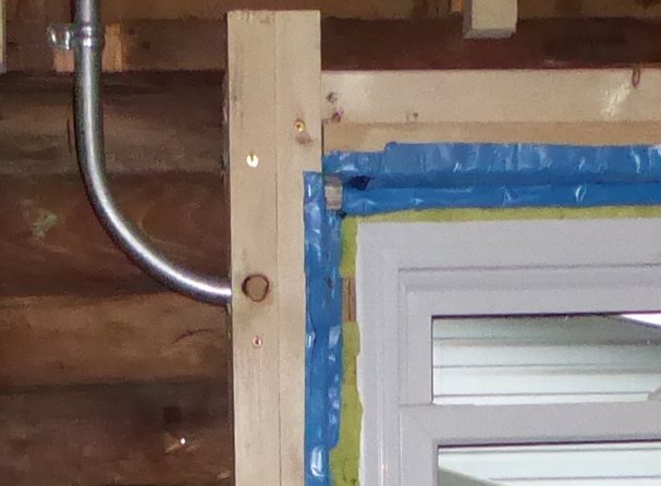
These conduits lead to the main wiring box of the area. Useful not only for sensors, but also electric blinds and curtains.
Motion sensors are installed a similar way. The motion sensor in my living room, for example, provides protection against intrusion from the outside via any of the windows on the exterior walls. Nothing special here as one would expect to see this as part of any security system. Except here the zone status of that sensor is also fed to Home Assistant.
An interior hallway or windowless room (even a closet) will have a motion sensor installed connected to an I/O board for the singular purpose of providing a motion input to the automation.
I make fairly extensive use of these sensors to automate lighting which, lets face it, is about 85% of the use of any home automation platform in one way or another. More information of how I use these sensors can be found under Automations.
Climate Control/HVAC |
As I have alluded to in the technical HVAC control description, I use no physical "thermostat". After considering the options and implementing a temporary control based around a simple relay controller and the Home Assistant generic thermostat it become rather permanent when I discovered that a physical (smart) thermostat control is largely pointless. Maybe I'm weird (maybe?!) because I don't find I ever need to adjust the temperature once it is set. I essentially want 4 different temperatures at any one time; "summer day", "summer night", "winter day", "winter night". Add an additional "away" temperature to both "summer" and "winter" if I am away from the house to avoid wasting heating/cooling energy. Of course there is also a period in the autumn and spring where the temperature and humidity are temperate enough that there is no need to adjust them.
I should mention that I live in Southwestern Ontario, Canada. As such we can have a temperature swing of 60℃ or more from the coldest days in the winter to the hottest days in the summer. There absolutely can be winter days colder than -30℃ juxtaposed by summer days above +30℃. Humidity typically lands somewhere around 25% in the winter to high 90s in the summer. As an aside, many meteorologists in Canada use a stupid measurement called "humidex" to express a different set of temperatures based on a calculated way we should "feel" the temperature vs. the actual temperature. This flawed system results in ridiculously wrong numbers being reported and general confusion. The real temperature could be +3℃ but the "humidex" value indicates it "feels like" -8℃ due to factors like wind and humidity. So you end up with people saying it is -8℃ when it really is +3℃. And then misunderstanding that the "humidex" only relates to how it feels to a person, mechanical devices such as thermostats. It is a stupid system invented by idiots perpetuated by morons. Rant over.
Unfortunately the Home Assistant Generic Thermostat isn't as smart as it should be. A thermostat can cool, or heat, but not both. This means that two thermostats must be used to support both heating and air conditioning. When I began with HA, there was no hygrostat integration. As such humidity control required either a set of automations, or a little trick to fool the generic thermostat into controlling humidity. As of release 2021.8, a generic hygrostat was added allowing native humidity control from HA.
I'll start with temperature control. The Generic Thermostat requires a temperature source (sensor), and then switches to control the physical HVAC device. First, let's start with the necessary sensors:
configuration.yaml:
mqtt:
  sensor:
###########Living Room Climate sensor
    - name: "Living Room Temperature"
      unit_of_measurement: "°C"
      state_topic: "tele/livingroomclimate/SENSOR"
      value_template: "{{value_json['AM2301'].Temperature }}"
    - name: "Living Room Humidity"
      unit_of_measurement: "%"
      state_topic: "tele/livingroomclimate/SENSOR"
      value_template: "{{value_json['AM2301'].Humidity }}"
############# There are a bunch more like this for several key areas of the house such as
############# bedroom, kitchen, basement. Multiples allow redundancy, more data points, etc.
template:
  - sensor:
        ########CLIMATE CONTROL TEMP SENSOR WITH FAILOVER
      - name: "Climate Control Temp Sensor"
        unit_of_measurement: '°C'
        state: >-
          {% set OutputTemp = 15 %}
          {% if states('sensor.bedroom_temperature') != 'None' %}
          {% set OutputTemp = states('sensor.bedroom_temperature')%}
          {% endif %}
          {% if states('sensor.kitchen_temperature') != 'None' %}
          {% set OutputTemp = states('sensor.kitchen_temperature')%}
          {% endif %}
          {% if states('sensor.basement_temperature') != 'None' %}
          {% set OutputTemp = states('sensor.basement_temperature')%}
          {% endif %}
          {% if states('sensor.living_room_temperature') != 'None' %}
          {% set OutputTemp = states('sensor.living_room_temperature')%}
          {% endif %}
          {{OutputTemp}}
|
There's a bit to unpack here and much of this is still in progress so it is only the very basics of a planned HVAC implementation. First, there are a number of "temporary" temperature & humidity sensors throughout the house in key locations. These may occasionally fail to provide a valid reading and instead simply return "None". Put simply, they suck. But they are the quickest and dirtiest way to get temperature data from areas in which permanent automation has not yet been completed. These are defined as MQTT sensors with a value_template to extract the data provided once per minute on a published MQTT topic "tele/(device)/SENSOR" from TASMOTA. Temperature and humidity are provided on the same topic serialized into a JSON payload. The temperature and humidity values are then broken out into individual sensor entities.
Below the physical sensors (only one example is provided here as the rest in different areas are the same save the MQTT topic), there is a template sensor "Climate Control Temp Sensor" defined. Its entire purpose is to provide a sensor entity for the generic thermostat to obtain its needed temperature input. But why all the complication? Why not just feed it with "Living Room Temperature? The aforementioned issue of the sensors randomly returning "None" instead of a valid temperature.
My ugly workaround for this is to use multiple sensors and just fail over to the next best reading upon the preferred sensor returning "None". This is done in the "value_template" where the value for "Climate Control Temp Sensor" is calculated. A variable "OutputTemp" with a value of "15" is defined as a "default" temperature output for the sensor. Why 15? Why not? That variable is successively assigned values from the preferred temperature sensor if that sensor value is not being returned as "None". It's a bit confusing because the preferred sensor as at the bottom. This is because the template is processed top down. So if the reading from "sensor.bedroom_temperature" is not ( != ) "None" (and it never will be as bedroom_temperature is a reliable sensor connected to my 1284board) it is then assigned to OutputTemp. This continues for several more sensors until the preferred sensor at the bottom of the template is reached. sensor.living_room_temperature is the ideal sensor for HVAC control as it represents the best average temperature of the house. In this way, sensor.climate_control_temp_sensor is tolerant of up to 3 sensor failures while still providing a reading from always the most preferred sensor. It's a bit of a ridiculous hack though for now, it does the job.
The generic thermostat requires a switch which when toggled, controls the HVAC device. All of these are provided by my HVAC controller board as MQTT switches:
configuration.yaml:
mqtt:
  switch:
    ############HVAC / furnace control board switches
    ##########HVAC AND CLIMATE SWITCHES
    #######HOUSE FURNACE/AC CONTROL SWITCHES
    - name: "Heating"
      state_topic: "/furnace/heatstate/"
      command_topic: "/furnace/heat/"
      payload_on: "1"
      payload_off: "0"
      qos: 0
      retain: true
    - name: "Cooling"
      state_topic: "/furnace/coolstate/"
      command_topic: "/furnace/cool/"
      payload_on: "1"
      payload_off: "0"
      qos: 0
      retain: true
    - name: "Blower"
      state_topic: "/furnace/blowerstate/"
      command_topic: "/furnace/blower/"
      payload_on: "1"
      payload_off: "0"
      qos: 0
      retain: true
    - name: "Humidifier Switch"
      state_topic: "/furnace/humidifierstate/"
      command_topic: "/furnace/humidifier/"
      payload_on: "1"
      payload_off: "0"
      qos: 0
      retain: true
|
Just the standard MQTT switch definitions above. One switch for each function of the HVAC. Note that as mentioned in HVAC the controller employs internal logic to prevent incompatible functions from being activated at the same time. So there is no way to turn on both the cooling and heating function simultaneously.
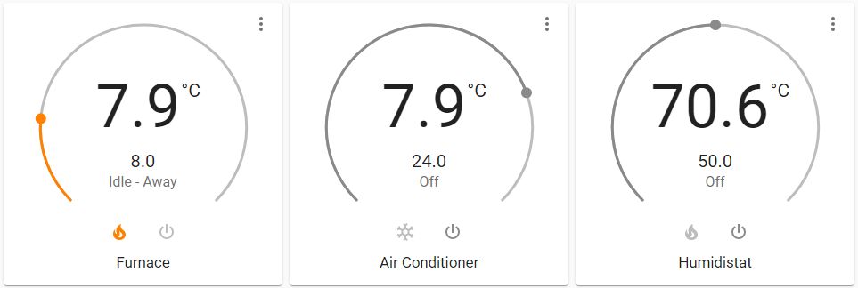
And finally, the thermostats themselves!
configuration.yaml:
############FURNACE
climate:
  - platform: generic_thermostat
    name: Furnace
    heater: switch.heating
    target_sensor: sensor.climate_control_temp_sensor_template
    min_temp: 3
    max_temp: 30
    ac_mode: False
    target_temp: 22.0
    cold_tolerance: 0.5
    hot_tolerance: 0.5
    min_cycle_duration:
      seconds: 120
    #keep_alive:
    #  minutes: 3
    #initial_operation_mode: "off"
    away_temp: 8
###########AIR CONDITIONER
  - platform: generic_thermostat
    name: Air Conditioner
    heater: switch.cooling
    target_sensor: sensor.climate_control_temp_sensor_template
    min_temp: 5
    max_temp: 30
    ac_mode: True
    target_temp: 24.0
    cold_tolerance: 0.5
    hot_tolerance: 0.3
    min_cycle_duration:
      seconds: 120
    #keep_alive:
    #  minutes: 3
    #initial_operation_mode: "off"
    away_temp: 28
##############FAKE THERMOSTAT USED AS HUMIDISTAT
  - platform: generic_thermostat
    name: Furnace Humidistat
    heater: switch.humidifier_switch
    target_sensor: sensor.fakeout_humidity_as_temp
    min_temp: 0
    max_temp: 100
    ac_mode: False
    target_temp: 50
    cold_tolerance: 0.5
    hot_tolerance: 5
    min_cycle_duration:
      seconds: 120
  #   #keep_alive:
  #   #  minutes: 3
  #   #initial_operation_mode: "off"
  #   #away_temp: 6
|
The Home Assistant generic thermostat is capable of running a heating device, or a cooling device, but not both. This is an unfortunate limitation which will probably be corrected in the future. For the present, it means that a distinct thermostat is needed for heating and another for cooling. I'll cover that mysterious "Furnace Humidistat" "thermostat" a bit later.
As I write this, my HVAC implementation is extremely basic. Just thermostats doing thermostat things with home and away temperatures defined and some automations to enable the thermostat away mode when I leave the house, and set the thermostat off away on a known time schedule. I have not yet implemented any logic to automatically switch the system between heating and cooling mode as this switch really only happens twice per year and right now, as they say, I have bigger fish to fry with automation rather than "fix" something I can do myself in 2 seconds.
My ultimate goal is to have a generic thermostat defined for every room of the house reading local temperature via the appropriate sensor (DHT22s on I/O boards typically) controlling a switch which is actually a motorized duct damper. Thereby creating a targeted heating and cooling system that can intelligently control the temperature specific to the requirements of the room or area. For example, during summer very little cooling is actually needed in the basement by virtue of it being mostly underground. While the living room of the house with a South facing wall full of windows requires full cooling capability. Though my bedroom is on the opposite side of the house with the door nearly always closed and is equipped with two HVAC registers as many years ago it was two rooms made into one. In this scenario I can imagine the air conditioner running with the basement duct baffles closed, living room baffles open and sometime during the cycle, bedroom baffles closing as desired temperature has been reached. This hasn't been implemented yet because I've not yet finalized my HVAC system. I may just dump the entire forced air unit, move to a condensing boiler and install an A/C unit (air handler) in the attic.
Now, about that "Furnace Humidistat" thermostat. Home Assistant until 2021.8 did not include a generic hygrostat for humidity control. However as a hygrostat is simply a "thermostat for humidity" there's absolutely no reason that we can't just use a generic thermostat to control a furnace mounted whole home humidifier. Except that the generic thermostat must receive a temperature input. This is easy to solve with a sensor that simply represents a humidity value in percent as a temperature value in ℃ :
configuration.yaml:
mqtt:
sensor:
#########fake sensor to represent humidity as temp for humidistat
- name: "Fakeout Humidity As Temp"
unit_of_measurement: "�C"
state_topic: "tele/livingroomclimate/SENSOR"
value_template: "{{value_json['AM2301'].Humidity }}"
|
All I'm doing is taking the MQTT value of a DHT22 based humidity sensor in the living room and setting the unit of measurement to ℃ . sensor.fakeout_humidity_as_temp can now be fed to generic_thermostat.furnace humidifier which is configured as a heating thermostat. Thus is switches switch.humidifier_switch on when the received humidity value (represented as a temperature) is below the set point, and switches it off when it is above. This works perfectly with the only weirdness being that an entity called a "Furnace Humidistat" shows its value in ℃ . The same effect could simply be created by an automation based the state of the humidity sensor but the generic thermostat comes with all of that pre-programmed and a set of services with a GUI. A humidity of 50% is desired and I've never had to adjust the humidistat.
To prevent the humidifier drum from spinning anytime the humidity falls below the persentage setpoint of the "hygrostat", I just use automations to switch the Furnace Humidistat on/off based on the state of the furnace:
configuration.yaml:
############ HVAC template sensors
template:
  - sensor:
      - name: "Air Conditioner State"
        state: "{{ states.climate.air_conditioner.attributes['hvac_action'] }}"
      - name: "Furnace State"
        state: "{{ states.climate.furnace.attributes['hvac_action'] }}"
|
automations.yaml:
#######FURNACE HUMIDIFIER ON
###turn on the generic thermostat used as humidistat when the furnace is heating
- alias: Furnace Humidifier On When Heating
  id: '904576239561238963478568934623'
  trigger:
  - platform: state
    entity_id: sensor.furnace_state_sensor
    to: 'heating'
  action:
  - data:
      entity_id: climate.furnace_humidistat
    service: climate.turn_on
######FURNACE HUMIDIFIER OFF
- alias: Furnace Humidifier Off When Not Heating
  id: '84423356464564545454223'
  trigger:
  - platform: state
    entity_id: sensor.furnace_state_sensor
    from: 'heating'
  action:
  - data:
      entity_id: climate.furnace_humidistat
    service: climate.turn_off
|
I both an AC state and furnace state template sensor defined as I use the states of the HVAC devices in a bunch of automations so it is a lot easier than every time needing to make a template to retrieve the hvac_action attribute. Therefore the Furnace "Humidifier On (and off) When Heating" automations just call the climate.turn_on or climate.turn off service for the climate.furnace_humidistat entity depending on whether sensor.furnace_state_sensor changes to "heating" (climate.turn_on) or from "heating" (climate.turn_off). And absolutely, this could be a single automation just triggering on sensor.furnace_state_sensor state change, then using a service_template action and some "if" statements. Items for future automation cleanup/consolidation.
Presence Detection |
Knowing when someone is home is a fundamental aspect of home automation which allows the house to configure itself to the occupants. From automatically turning off lights after everyone leaves, to setting climate control to "away" mode, or sending specific alerts if something happens which shouldn't if no one is home (why is the water running if there aren't humans in the house?!). Unfortunately it is almost one of the most difficult things to achieve because it is shockingly hard to reliably and unobtrusively track a creature with free will to make their own decisions. Other than stitching some sort of transmitting beacon into one's skin (and yes, I have an RFID tag implanted in my hand, but that is useless for tracking with a range of a few inches at best) or equipping every area of the house with a person recognizing camera system, the best unobtrusive method of presence detection in my experience seems to be tracking the symptoms of people, not the people. For me, this means tacking the location of my mobile. There are only a few instances in the last 27 years in which I have left the house without my BlackBerry so one can reasonably assume that the location of my BlackBerry is the location of myself.
Thankfully Home Assistant provides multiple methods which can be used to track a mobile device. The two integrations for device tracking I use are Nmap Tracker and GPSLogger. These are used in combination with a Person integration to provide a person entity representing my location and whether I am home/not_home.
My Nmap Tracker configuration is fairly standard. At some point the nmap integration configuration moved from configuration.yaml to the UI:
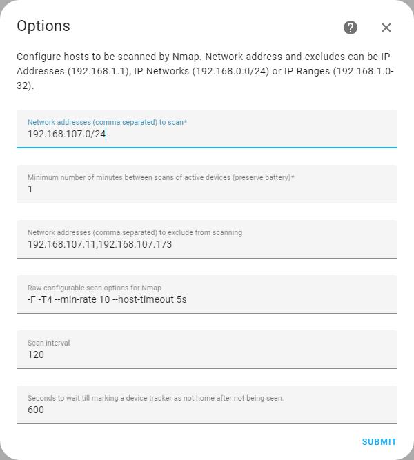
The integration configures Home Assistant to use NMAP to scan my entire IP subnet (I'm assuming it runs an ARP scan, though I have never bothered to read the detailed documentation to verify this) every 120 seconds. That means the longest time I would have to wait to be recognized at home is 2 minutes in the event that I am on the WiFi network just as the last scan finishes and therefore must wait for the next.
Home Assistant then creates an entity for each device found on the network. From there, tracking can be enabled to track needed devices.
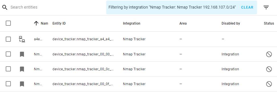
The entity top entity in the list represents the device tracker used by the NMAP tracker to track my BlackBerry Classic by MAC address.
There is no YAML configuration for the GPSLogger integration. All configuration is is done within the GUI and there really isn't anything to configure. Once the integration is enabled a webhook is provided for each device authorizing it to send data to HA via HTTP/HTTPS. The GPSLogger integration creates the devices (which creates a corresponding entity) based upon the webhook provided (with the user configures in the GPSLogger app). "Aaron BB Classic GPS Logger" is therefore the device tracker entity corresponding to my BlackBerry GPS location. It exposes GPS coordinates and a few other handy parameters (battery level, speed, altitude, etc.).
The GPSLogger app is configured to post the GPS location of my BlackBerry Classic to the Home Assistant webhook generated by the integration every 5 minutes. As such it could at anytime be at least 5 minutes behind where I currently am. I say "at least" because if GPSLogger cannot get a GPS satellite lock there could be significant inaccuracy in my location. Consider the scenario of driving at 100KM/H, pulling off the expressway and then entering a warehouse where no satellites are visible. Assuming I entered the building at minute 5, my last location could be 8KM away and not update for up to 5 minutes after I have left the building. I don't find this to be much of an issue because I'm typically not creating automations based upon me being in a building other than home. At least, I haven't yet.
These two device trackers feed into the HA Person Integration to create a person entity named "Aaron" which represents my current location, whether I am home or somewhere else. I have the Person integration configured in YAML though I believe there is a GUI configuration available as well.
configuration.yaml:
##########################################################################################
# PEOPLE
##########################################################################################

person:
  - name: Aaron
    id: ac021380
    user_id: a86076fxxxxxxxxxxxxxxxxxxxxx5105
    device_trackers:
      - device_tracker.nmap_tracker_a4e_4_xxxxxxxx
      - device_tracker.00xxxxxxxxxxxxxxxxxxx1_x
|
Now the Person integration has one significant flaw: there is no service call nor other way to manually set the state of a person. This means that it is difficult to integrate devices/entities states as a source to determine whether a person is home or not. The "device_trackers" list can only be device trackers, and not an alarm panel state, for example. I can reasonably assume that whenever my alarm panel state changes to "disarmed", I am home. Since the Person integration cannot respond to this state change the standard solution is a bit of a convoluted work around (which I have not implemented yet):
Hopefully in the future, a service will be introduced to allow programmatic setting of Person integration to render this silliness unnecessary.
Power Monitoring |
Power monitoring right now is at an extremely basic level and I really don't use the data for anything other than display at the moment. Per sensors I have a DIY power monitor based upon the CircuitSetup Expandable 6 Channel ESP32 Energy Meter Main Board, STM32 "Blue Pill", W5500 Ethernet and 2.2" ILI9225 based SPI TFT screen.
Power monitor data for the following is published every 2 seconds via MQTT: currents phase 1 & 2, total current, voltages phase 1 & 2, total voltage, wattage for phases 1 & 2, total wattage, mains frequency, power factor, power monitor temperature.
In Home Assistant, this data is consumed by a series of MQTT sensors:
configuration.yaml:
#########POWER MONITORING SENSORS
mqtt:
  sensor:
    - name: "Power Grid Voltage Phase 1"
      state_topic: "/energymon/energy/"
      value_template: "{{ value_json.VltA }}"
      unit_of_measurement: "V"
    - name: "Power Grid Voltage Phase 2"
      state_topic: "/energymon/energy/"
      value_template: "{{ value_json.VltC }}"
      unit_of_measurement: "V"
    - name: "Power Grid Total Voltage"
      state_topic: "/energymon/energy/"
      value_template: "{{ value_json.TtlV }}"
      unit_of_measurement: "V"
    - name: "Power Grid Current Phase 1"
      state_topic: "/energymon/energy/"
      value_template: "{{ value_json.CT1 }}"
      unit_of_measurement: "A"
    - name: "Power Grid Current Phase 2"
      state_topic: "/energymon/energy/"
      value_template: "{{ value_json.CT2 }}"
      unit_of_measurement: "A"
    - name: "Power Grid Total Current"
      state_topic: "/energymon/energy/"
      value_template: "{{ value_json.TtlCur }}"
      unit_of_measurement: "A"
    - name: "Power Grid Wattage Phase 1"
      state_topic: "/energymon/energy/"
      value_template: "{{ value_json.CT1W }}"
      unit_of_measurement: "W"
    - name: "Power Grid Wattage Phase 2"
      state_topic: "/energymon/energy/"
      value_template: "{{ value_json.CT2W }}"
      unit_of_measurement: "W"
    - name: "Power Grid Total Wattage"
      state_topic: "/energymon/energy/"
      value_template: "{{ value_json.TtlW }}"
      unit_of_measurement: "W"
    - name: "Power Monitor Temp"
      state_topic: "/energymon/energy/"
      value_template: "{{ value_json.ChpTmp }}"
      unit_of_measurement: "°C"
    - name: "Power Grid Line Frequency"
      state_topic: "/energymon/energy/"
      value_template: "{{ value_json.LinFrq }}"
      unit_of_measurement: "Hz"
|
The result is a very simple dashboard showing current power data:
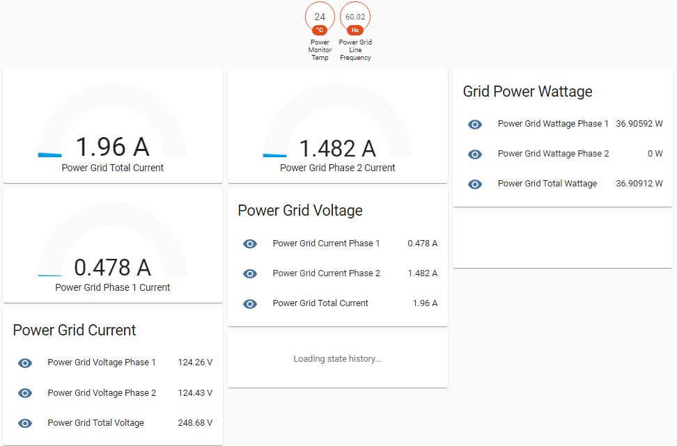
And you'll notice that the history graphs are not populated. Unfortunately, even with all the database improvements in release 2022.4, retrieving often updated (every 2 seconds) data and processing it for display is extremely inefficient with a lot of handling in code (vs. the database engine) and a lot of client (browser) side work for rendering. History graphs of many data points almost always fail to render. I hope to deal with this in the future when I expand the energy monitor to cover a planned solar system.
In release 2021.8 Home Assistant introduced the Energy Dashboard which provides a dedicated dashboard for all energy related monitoring. Distribution, historical use, use per source, etc. are all integrated into one straightforward dashboard. Data comes from energy monitoring sensors and long term statistics are generated. The Energy Dashboard is not a function I have yet implemented as my energy monitoring isn't finalized so I've never bothered to configure it.
You may also notice that "Power Grid Wattage Phase 2" is showing zero. At the time I took the screenshot, there was a small mistake in my code.