| Home > My Projects > Home Automation > DIY Power Bars and Outlets |
| Home > My Projects > Home Automation > DIY Power Bars and Outlets |
Some of my first automation related hardware projects were a DIY "smart" power bar, and a set of DIY "smart" outlets. The power bar was based on an Arduino Nano, ENC28J60 Ethernet shield and 2 relay modules. The outlets were based on ESP8266 ESP-01S relay modules which are commonly available on eBay, Aliexpress and other marketplaces.
Nano ENC28J60 Ethernet Power Bar |
This was actually the first device I ever integrated into Home Assistant. I used it for about a year to control two lamps in my living room. It was mainly created as a test project to get used to how Home Assistant represents devices, and to create simple automations.
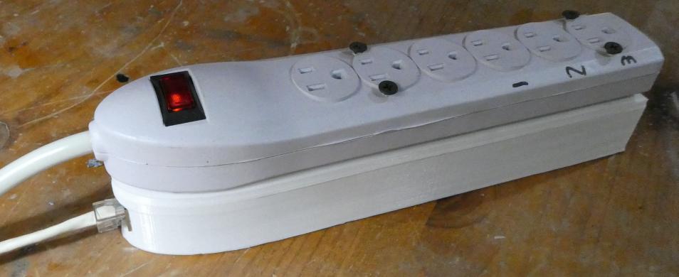
I started with a cheap power bar from a local surplus store. A new base was designed and then 3D printed to contain an Arduino Nano mounted on an ENC28J60, a 5V power supply salvaged from an old Samsung phone charger, and two relay modules (a single and dual module were used to fit into the available space.
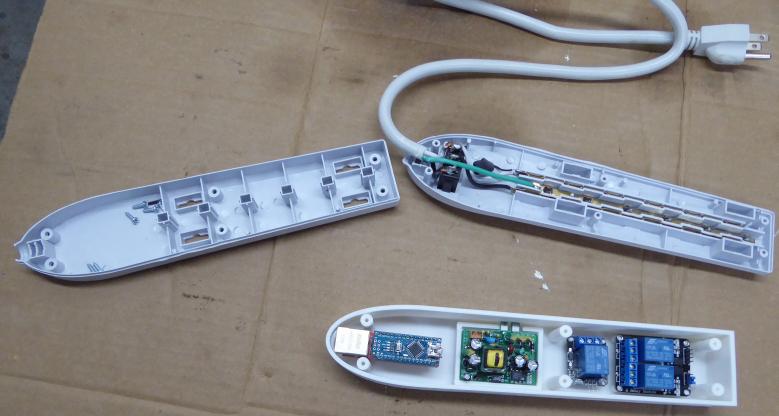
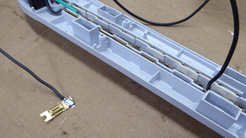
From the factory, the power bar was a simple arrangement of two pressed copper strips which have been stamped to form the prong sockets. I wanted 3 controllable outlets on the bar out of the 6 provided. To accomplish this, I cut the last three sections of the hot side bar apart then soldered wires to them. They were then re-inserted into the bar. Thus separating the last three sockets into their own circuits.
The power bar was reassembled after some holes were drilled into the bottom. I would have liked to simply design and 3D print another bottom cover that was integral to the electronics enclosure but the bottom cover was actually the second half of a clamp which secured and tensioned all of the plug sockets and their rails as well as providing strain relief for the cord. I don't think I could have printed parts both thin and strong enough. Plus of course, one would hope that the power bar casing is some sort of certified and fire resistant plastic which I couldn't replicate.
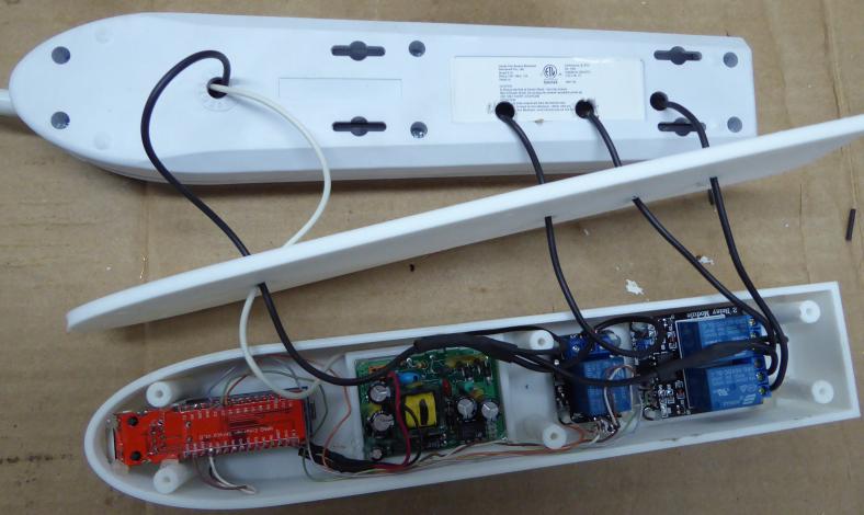
I split the hot wire coming from the power bar master switch into three leads which connected mains side of the 5V power supply board and the three relay common contacts. Each relay NO contact was connected to one of the leads from the plug sockets. A neutral lead from the power bar completed the circuit to the power supply mains side. And finally, Arduino Nano pins D2, D3 and D4 were accessed from the Ethernet bottom shield side and connected to the relay modules corresponding trigger pins.
The firmware running on the Nano is just an earlier version of my MQTT I/O controller boards firmware using the UIPEthernet library. Thus in Home Assistant the outlets could be configured as MQTT Lights or MQTT Switches for example.
I was very happy with this power bar for about 8 months. It sat in my living room, controlling a table lamp. And then, like every project I have ever done using the ENC28J60, it started becoming intermittent and losing network connectivity. This is when I started to find that there are widespread issues with the ENC28J60. There are many reports of freezes and lockups, lots of known errata with the silicon, and major quality issues with many of the shields/modules. After wasting some time troubleshooting the lockups, during which I could naturally never reproduce with a computer reading debug info from the Nano only to have it fail the next day, I replaced the power bar with a Geeni GNC-SW003. There was definitely some irony in replacing the reliable Ethernet based power bar with a potentially unreliable WiFi power bar because the Ethernet chipset itself wasn't reliable.
ESP8266 ESP-01S Relay Outlets |
I had previously purchased a bunch of ESP8266 ESP-01S relay modules because I thought they might be useful where I needed a single quick and dirty point of control or to integrate into something needing remote control. So when I needed a few temporary controllable outlets I used them in combination with a 5V power supply to build some simple controllable outlet boxes.
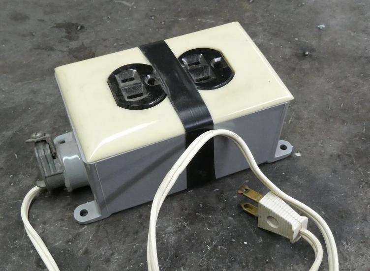
The construction was very simple as it was all done with items I had on hand. Within a single gang PCV device box, I mounted a 5V power supply module and the relay module with some hot glue. A discarded appliance line cord was used with the neutral split to feed the power supply module and the neutral side of a standard single gang outlet. The hot lead was split to feed the power supply and the common side of the relay module contacts. And the normally open side of the relay contact then connected to the hot side of the outlet. There was no added method of manual control via a switch nor button. Needless to say, having only two prong cords, these are only to be used for light loads not requiring a grounding connection. The purpose is for lamps and such.
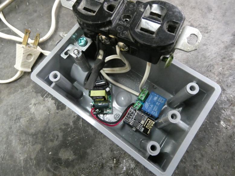
I programmed the ESP8266-01S module with whatever the current version of Tasmota was at the time. The relay is connection to GPIO0 and set to Relay1i. Tasmota is configured for MQTT and thus represents the relay as MQTT topic cmd/tasmota/POWER with payloads "ON" and "OFF".
These have been extremely reliable considering the parts used and have found their primary use as controlling Christmas lights at my parent's house (a VPN between the two houses allows my Home Assistant/MQTT to be shared for little conveniences like these).
Incidentally, there are several version of these little relay modules available. If you want to use one, make sure to get the version where the terminal blocks are beside the relay and the ESP8266 module is mounted perpendicular to the length of the board. There is another longer version where the ESP8266 module is mounted lengthwise and the terminal blocks are more spread out. That version actually connects the ESP8266 serial port to an intermediate STM32 processor which takes commands to control the relay. This version is much more annoying to use instead of just having a GPIO connected to the relay via a transistor.