| Author |
 Topic Topic  |
|
JUAN DELA CRUZ
Mad Scientist
   
Philippines
476 Posts |
 Posted - Aug 25 2008 : 04:47:37 AM Posted - Aug 25 2008 : 04:47:37 AM


|
Oooops SORRY...
Miscommunication INDEED
..English is not my tough language.
So, another flip-flop ckt. is not needed 'coz the op-amp with hysteresis is also a flip-flop.
quote:
The circuit I gave you was a 741 with hysteresis.
You mean THIS ckt. ?

Is it OK if I use LM324 instead of 741 ?
('coz the other op-amp was used in MSW ckt.)
BTW..
I realize when the battery voltage reaches 11V, it is almost dead.
That's why I change it to cut-off when the battery voltage isr
approx. 11.5V
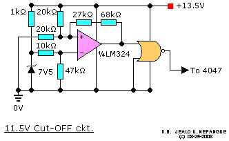
And THIS ckt. was the result.

Download Attachment:  11.5V Cut-OFF ckt. _FLIP-FLOP.GIF 11.5V Cut-OFF ckt. _FLIP-FLOP.GIF
4.18 KB
Thank you
|
juan dela cruz
Penniless INVENTOR |
 |
|
|
pebe
Nobel Prize Winner
    
United Kingdom
1078 Posts |
 Posted - Aug 25 2008 : 11:51:16 AM Posted - Aug 25 2008 : 11:51:16 AM


|
Yes, you can use the LM324 instead of the 741.
The values of 10K and 47K across the 7.5Vzener give a voltage of 6.18V. The calculated voltage required is 6.12V, but that's near enough not to make any difference. |
 |
|
|
JUAN DELA CRUZ
Mad Scientist
   
Philippines
476 Posts |
 Posted - Aug 26 2008 : 09:57:46 AM Posted - Aug 26 2008 : 09:57:46 AM


|
Greetings...
Do you think a MC34074 can be use in my 11.5V cut-off ckt. instead of LM324 ?
I will the detection ckt. in my MSW ckt. ...( Click HERE )
Thank you |
juan dela cruz
Penniless INVENTOR |
 |
|
|
pebe
Nobel Prize Winner
    
United Kingdom
1078 Posts |
 Posted - Aug 26 2008 : 10:14:55 AM Posted - Aug 26 2008 : 10:14:55 AM


|
| I should think it will replace the LM324 in that circuit. Try it. |
 |
|
|
pebe
Nobel Prize Winner
    
United Kingdom
1078 Posts |
 Posted - Aug 27 2008 : 03:46:46 AM Posted - Aug 27 2008 : 03:46:46 AM


|
| I don't even know whether the circuit will work. Why not ask whoever designed it? |
 |
|
|
JUAN DELA CRUZ
Mad Scientist
   
Philippines
476 Posts |
 Posted - Aug 27 2008 : 04:06:53 AM Posted - Aug 27 2008 : 04:06:53 AM


|
quote:
Originally posted by pebe
I don't even know whether the circuit will work. Why not ask whoever designed it?
Greetings..
Actually, I am the one who make this diagram.
In related with the thread I'd started entitled "CD4047: Varying the Pulse-width".
And also the 555 variable lenght monostable ckt. of yours.
(indicated in the diagram above).
Used for compensation for battery voltage variation to obtain voltage regulation in a MSW Inv.
*The output from the 555 variable lenght monostable ckt. is integrated to triangular wave and have that triangular wave into the non-inverting input of the comparator & the DC voltage (from Inv. Output) in the inverting input to 'sense' the varying LOAD...
You said the idea is possible.
But I have some confusion about the components value esp. with (?).
( Click here )
I used a 4N25 for isolation of the output.
As audioguru suggested me to use.
I shift to MC34074 and I added a mosfet driver LM3111.
Thank you |
juan dela cruz
Penniless INVENTOR |
Edited by - JUAN DELA CRUZ on Aug 27 2008 04:30:57 AM |
 |
|
|
pebe
Nobel Prize Winner
    
United Kingdom
1078 Posts |
 Posted - Aug 27 2008 : 06:45:02 AM Posted - Aug 27 2008 : 06:45:02 AM


|
I said the IDEA is POSSIBLE - not that your circuit would work. To use an old expression you are 'trying to make a silk purse from a sow's ear'.
Look in that thread for my replies of Aug8 at 5.40 and Aug10 at 8.48.
I think you are wasting your time trying to give your simple inverter automatic regulation for varying loads. That needs a more complex switched inverter. |
 |
|
|
JUAN DELA CRUZ
Mad Scientist
   
Philippines
476 Posts |
 Posted - Aug 28 2008 : 01:37:20 AM Posted - Aug 28 2008 : 01:37:20 AM


|
Greetings..
I'd tested the drive ckt. with feedback by opto-isolator but still the output voltage dropped as the load increases.(NO EFFECT)
But, I've noticed that the reason of output voltage dropping was due to "late activation of the low battery detection ckt."
(I used my previous low batt. cut-off ckt. with relay
I mean IT only needs to turn-off the inverter more advance
(i.e. when the battery voltage is less than 12V approx. 11.9V)
& the 555 variable lenght monostable ckt. will do th rest of adjustment to the pulse to regulate the average output voltage when the battery is charged.
Regarding my low battery detection ckt. without the relay..
Do you think when the detection ckt. was activated it will retain its state...
I mean.. when IT turn-off the inverter
('coz it sense that the battery is low)
... when it happens the battery voltage will rise because the load (inverter) is off. Or oscillation will occur.
So, do you think it really needs another flip-flop to prevent this for happenings ?
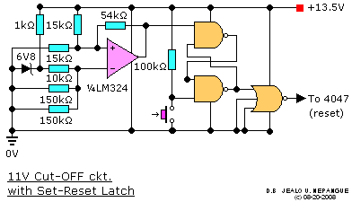
Like this one:
Download Attachment:  Low Battery detection Ckt.GIF Low Battery detection Ckt.GIF
9.39 KB

Thank you |
juan dela cruz
Penniless INVENTOR |
 |
|
|
pebe
Nobel Prize Winner
    
United Kingdom
1078 Posts |
 Posted - Aug 28 2008 : 02:45:49 AM Posted - Aug 28 2008 : 02:45:49 AM


|
In the circuit I gave you, the battery cuts out at 11.5V and won't cut in again until the battery reaches 13.5V. It will never reach that until it is recharged.
So:
1. No, it will not oscillate.
2. You do not need a second flip-flop.
|
 |
|
|
JUAN DELA CRUZ
Mad Scientist
   
Philippines
476 Posts |
 Posted - Aug 28 2008 : 03:29:02 AM Posted - Aug 28 2008 : 03:29:02 AM


|
Greetings..
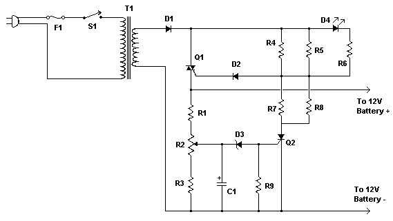
Could this charger can be modify to have no transformer ?
If not do you know a transformerless battery charger ?

Download Attachment:  Battery Charger.gif Battery Charger.gif
4.29 KB
Thank you
|
juan dela cruz
Penniless INVENTOR |
 |
|
|
pebe
Nobel Prize Winner
    
United Kingdom
1078 Posts |
 Posted - Aug 28 2008 : 04:16:13 AM Posted - Aug 28 2008 : 04:16:13 AM


|
quote:
Originally posted by JUAN DELA CRUZ
Could this charger can be modify to have no transformer ?
No.quote:
If not do you know a transformerless battery charger ?
No.
|
 |
|
|
JUAN DELA CRUZ
Mad Scientist
   
Philippines
476 Posts |
 Posted - Aug 28 2008 : 04:21:09 AM Posted - Aug 28 2008 : 04:21:09 AM


|
quote:
Originally posted by pebe
In the circuit I gave you, the battery cuts out at 11.5V and won't cut in again until the battery reaches 13.5V. It will never reach that until it is recharged.
So:
1. No, it will not oscillate.
2. You do not need a second flip-flop.
Do you think IT can turn-off the reset (Pin9_4047) & the third input of a 4025 ? ..'coz I am planning to turn-off them simultaneously to make sure that the FETs are off when the battery voltage is low.
*Regarding the 555 Ckt.
..which is better in my application CMOs type or Bipolar ?
quote:
Originally posted by pebe
You need two different controls.
1. A relay that will switch on the inverter when mains is not available. When mains is available the battery will be automatically charged and the inverter switched off.
2. A 2 level detector that (when no mains is available and the inverter is being used) switches off the inverter when battery voltage has dropped to 11V, and switches it on when battery reaches 13V.
How can I turn off the charger when the battery is fully charge ?
..another detection Ckt. ?
Thank you |
juan dela cruz
Penniless INVENTOR |
Edited by - JUAN DELA CRUZ on Aug 28 2008 04:24:37 AM |
 |
|
|
pebe
Nobel Prize Winner
    
United Kingdom
1078 Posts |
 Posted - Aug 28 2008 : 07:05:36 AM Posted - Aug 28 2008 : 07:05:36 AM


|
quote:
Originally posted by JUAN DELA CRUZ
Do you think IT can turn-off the reset (Pin9_4047) & the third input of a 4025 ? ..'coz I am planning to turn-off them simultaneously to make sure that the FETs are off when the battery voltage is low.
I see that the reset pin of the 4047 takes Q low and Q high. You need to make them both low to cut off the FETs. So wire it so the opamp output provides the 4047 +ve supply. When the opamp o/p goes low the 4047 will shut down.quote:
*Regarding the 555 Ckt.
..which is better in my application CMOs type or Bipolar ?
Either one.quote:
How can I turn off the charger when the battery is fully charge ?
..another detection Ckt. ?
Manually with a switch, or with a timer switch. |
 |
|
|
pebe
Nobel Prize Winner
    
United Kingdom
1078 Posts |
 Posted - Aug 29 2008 : 04:00:00 AM Posted - Aug 29 2008 : 04:00:00 AM


|
quote:
Originally posted by JUAN DELA CRUZ
You mean this Ckt. can't turn-off the 4047 through reset Pin9 ?
I thought it only need to a "High" to turn-off th driver.
Look at the data sheet.quote:
BTW.. What is the function of the second flip-flop in this Ckt. ?
I have no idea. |
 |
|
|
audioguru
Nobel Prize Winner
    
Canada
4218 Posts |
 Posted - Aug 29 2008 : 11:39:12 AM Posted - Aug 29 2008 : 11:39:12 AM


|
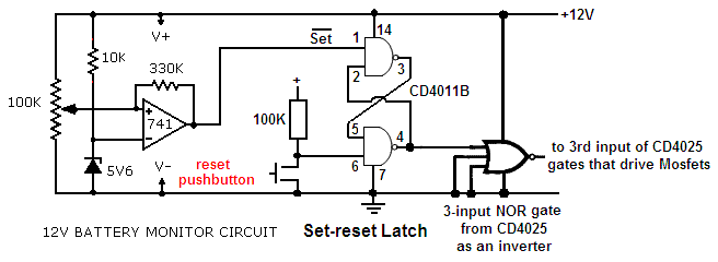
My circuit uses 3-input NOR gates to drive the Mosfets. This circuit drives the third input high which shuts off the Mosfets.
The opamp comparator SETS the flip-flop to turn off the Mosfets when the battery voltage is low. The flip-flop is manually RESET so that when the battery voltage rises when the inverter is turned off (when the battery voltage is detected low by the comparator) then the Mosfets are not turned on again.
The reset button is pushed to start the inverter when the battery is fully charged. |
 |
|
 Topic Topic  |
|

