| Author |
 Topic Topic  |
|
JUAN DELA CRUZ
Mad Scientist
   
Philippines
476 Posts |
 Posted - Aug 20 2008 : 05:07:44 AM Posted - Aug 20 2008 : 05:07:44 AM


|
quote:
Originally posted by pebe
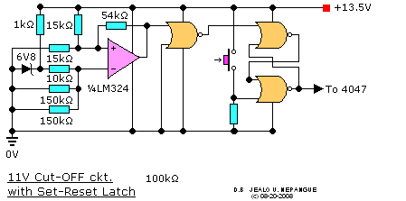
The o/p of the opamp is the wrong polarity. You need another NOR gate wired as an inverter placed in the feed to the top opamp.
Then apply the logic of using two NOR gates as a flip-flop and figure out how to wire up its four inputs.
Greetings..
I need to use " 2 NOR gates only" as the flip-flop.
The o/p of the Op-amp is from high to low..
-- how can I reverse the polarity of the op-amp ?
...reversing the +ve & -ve input ?
I think it will affect the feedback.
Thank you |
juan dela cruz
Penniless INVENTOR |
 |
|
|
pebe
Nobel Prize Winner
    
United Kingdom
1078 Posts |
 Posted - Aug 20 2008 : 05:33:47 AM Posted - Aug 20 2008 : 05:33:47 AM


|
| No, it won't work. |
 |
|
|
pebe
Nobel Prize Winner
    
United Kingdom
1078 Posts |
 Posted - Aug 20 2008 : 05:40:48 AM Posted - Aug 20 2008 : 05:40:48 AM


|
You have the o/p pin of an op-amp that goes low for the period when the battery is unusable.
You have an i/p pin of the 4047 that requires the exact opposite.
What do you need?
Think about it! |
 |
|
|
pebe
Nobel Prize Winner
    
United Kingdom
1078 Posts |
 Posted - Aug 20 2008 : 06:03:06 AM Posted - Aug 20 2008 : 06:03:06 AM


|
You said you need to use 2 NOR gates only. Now you have added another 2 ICs.
Why do you keep moving the goalposts? |
 |
|
|
JUAN DELA CRUZ
Mad Scientist
   
Philippines
476 Posts |
 Posted - Aug 20 2008 : 06:14:43 AM Posted - Aug 20 2008 : 06:14:43 AM


|
quote:
Originally posted by pebe
You said you need to use 2 NOR gates only. Now you have added another 2 ICs.
Why do you keep moving the goalposts?
Greetings..
What do you mean ?
There is a chance of using only two Logic gates (i.e. NOR gates) in my application?
quote:
You have the o/p pin of an op-amp that goes low for the period when the battery is unusable.
You have an i/p pin of the 4047 that requires the exact opposite.
Think about it!
Do you mean using an logic gate as an inverter (like in my recent post)? ...it uses another Logic gates.
I need to use two NOR gates only.
quote:
What do you need?
A pull-ups resistor ? ... just a guess 
-- To increase the "low" output from the op-amp at the specific point
to turn-off the Inv. through reset pin of the 4047.
*I am trying to improve my Simple MSW Inverter..
(no longer SIMPLE ) )
.. that's why I keep moving the goalposts and at the same time to improve my knowledge in Electronics.
Thank you. |
juan dela cruz
Penniless INVENTOR |
Edited by - JUAN DELA CRUZ on Aug 20 2008 06:37:48 AM |
 |
|
|
pebe
Nobel Prize Winner
    
United Kingdom
1078 Posts |
 Posted - Aug 20 2008 : 07:23:22 AM Posted - Aug 20 2008 : 07:23:22 AM


|
quote:
Originally posted by JUAN DELA CRUZ
[font=Arial][b][size=2]quote:
Originally posted by pebe
You said you need to use 2 NOR gates only. Now you have added another 2 ICs.
Why do you keep moving the goalposts?
Greetings..
What do you mean ?
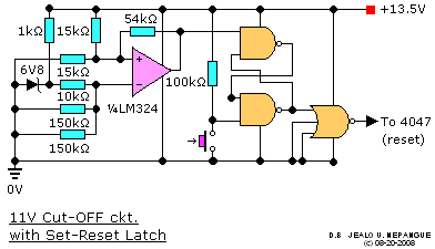
I mean you are now using a NAND gate plus a 3input NOR gate (you were only using 2input NOR gates before
quote:
There is a chance of using only two Logic gates (i.e. NOR gates) in my application?
No. Not just two as a flip flop.
quote:
quote:
You have the o/p pin of an op-amp that goes low for the period when the battery is unusable.
You have an i/p pin of the 4047 that requires the exact opposite.
What do you need?
Think about it!
Do you mean using an logic gate as an inverter (like in my recent post)? ...it uses another Logic gates.
Yes, a NOR gate on its own wired as an inverter will invert the signal to the needed one. |
 |
|
|
JUAN DELA CRUZ
Mad Scientist
   
Philippines
476 Posts |
 Posted - Aug 21 2008 : 03:23:15 AM Posted - Aug 21 2008 : 03:23:15 AM


|
Greetings...
I think it is better to use two ICs. (4011, 4025)
Using Quad NAND gates.. only two gates were used in the low btt. detection ckt.
..there are two unused NAND gates.
Can I use them as a touch switch (flip-flop ?) to turn-on/off the MSW inv. ( by a push-button switch )?
--- without using a relay---
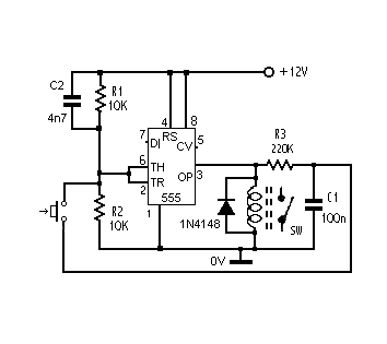
Just like this: ...but using two NAND gates instead

Thank you. |
juan dela cruz
Penniless INVENTOR |
Edited by - JUAN DELA CRUZ on Aug 21 2008 03:29:22 AM |
 |
|
|
pebe
Nobel Prize Winner
    
United Kingdom
1078 Posts |
 Posted - Aug 21 2008 : 04:58:07 AM Posted - Aug 21 2008 : 04:58:07 AM


|
Juan,
You seem to flip back and forward from one idea to the next.
You wanted a cutout with hysteresis to cut out on low battery volts and cut in again when full battery was restored. I gave you one.
You wanted a cutout with reset. I said you only needed a single gate wired as an inverter to connect my cutout to the 4047. You said:quote:
I think it is better to use two ICs. (4011, 4025)
You asked for advice and I gave it, but if you think your way is best, then go ahead. But you're on your own because I cannot keep up with your constantly changing circuit.
|
 |
|
|
JUAN DELA CRUZ
Mad Scientist
   
Philippines
476 Posts |
 Posted - Aug 22 2008 : 04:01:42 AM Posted - Aug 22 2008 : 04:01:42 AM


|
quote:
Originally posted by pebe
Juan,
You seem to flip back and forward from one idea to the next.
You wanted a cutout with hysteresis to cut out on low battery volts and cut in again when full battery was restored. I gave you one.
You wanted a cutout with reset. I said you only needed a single gate wired as an inverter to connect my cutout to the 4047. You said:quote:
I think it is better to use two ICs. (4011, 4025)
You asked for advice and I gave it, but if you think your way is best, then go ahead. But you're on your own because I cannot keep up with your constantly changing circuit.
Miscommunication..
Sir, I am really sorry for my constantly changing ckt.
The reason of this was I keep on trying to use lesser components as possible (i.e. less IC used, less cost).
quote:
You asked for advice and I gave it, but if you think your way is best, then go ahead. But you're on your own because I cannot keep up with your constantly changing circuit.
I didn't meant like that sir. What I meant when I said this:quote:
I think it is better to use two ICs. (4011, 4025)
...Using NOR gates in my cut-off ckt. as flip-flop will need another NOR gate wired as an inverter to turn-off Pin9 (reset)...right?
---three NOR gates in total---
..one IC contain only four NOR gates.
Before I am planning to use only one IC (4001).
One pair for MSW generation.. and the other pair for flip-flop ( which is not possible)
-- IT needs another NOR gate as a inverter--
That's why, I'd mention that "it is better to use two IC" (4011 & 4025).
Using 4025 3-input NOR gate... one pair will be use to generate MSW.
...and the unused gate gate will be use as an inverter.
Using 4011 Quad 2-input NAND gate.. a pair for flip-flip ckt.
... and the other pair (unused gates) which I am planning to use as
a touch switch (if possible).
Sir, I really acquired a lot of knowledge from you that I didn't learned from college.
That's why I am very grateful for your valuable time & effort spent with me.
Thank you very much
|
juan dela cruz
Penniless INVENTOR |
Edited by - JUAN DELA CRUZ on Aug 22 2008 05:09:13 AM |
 |
|
|
pebe
Nobel Prize Winner
    
United Kingdom
1078 Posts |
 Posted - Aug 22 2008 : 2:45:53 PM Posted - Aug 22 2008 : 2:45:53 PM


|
Juan, Letís backtrack.
Go back and look at page 1 of this thread that you started. You wanted to know the formulae for calculating hysteresis for a comparator. This, presumably, was in connection with your low battery detector.
The fact that you wanted to calculate hysteresis indicated you wanted a device that cut out when the battery was low and cut back in again when the battery was charged up. If you had only wanted a low-voltage cutout you could have just used a comparator/latch and there would have been no need for hysteresis.
I explained to you how to do all the calculations Ė but, in fact, after a lot of exchanges I ended up doing them myself and gave you the complete circuit using a 741 opamp!
Then you wanted some form of flip flop that turned off the 4047 when the battery was low, with a manual reset to turn it back on again.
I told you that all that was needed was just one gate wired as an inverter to invert the negative signal from the op-amp to make it a positive one to stop the 4047 oscillating. Yet you continue to ask questions about a flip-flop! What else do you expect me to say? Surely not to repeat the same stuff all over again?
Do me and yourself a favour. Go right back to the start of this thread and read and digest every line of every posting. Define to yourself EXACTLY what you want and make that your goal, and DO NOT deviate from that path!
If you then come up with valid questions I will do my best to answer them. If not, Iíll bow out of this discussion.
|
 |
|
|
JUAN DELA CRUZ
Mad Scientist
   
Philippines
476 Posts |
 Posted - Aug 23 2008 : 02:51:43 AM Posted - Aug 23 2008 : 02:51:43 AM


|
Greetings..
*The first reason why I'd started this thread is to have a Cut-off ckt. for my MSW Inv. ckt. when the battery voltage is too low.
*Secondly, to acquire knowledge on how a Op-amp works & how positive feedback (hysteresis) affect its operation.
*Thirdly, how can I apply THIS knowledge obtain in this basic concept with my MSW Inv. when I added a battery charger.
(i.e. automatically charge the battery when the battery voltage is low, and stop charging when the battery is fully charge)
To summarize THOSE above statements...
"MY GOAL IS TO BUILD AN MSW INV. THAT CAN ACT LIKE AN UPS"
..that is can be plug in the 'mains' for automatic charging (charge the battery when the IT is discharge and stop charging when IT is fully charge) & activate the MSW Inv. (when the mains are NOT available) & turn IT off when the battery voltage reached below 12V.
Thank you |
juan dela cruz
Penniless INVENTOR |
 |
|
|
JUAN DELA CRUZ
Mad Scientist
   
Philippines
476 Posts |
 Posted - Aug 23 2008 : 05:07:21 AM Posted - Aug 23 2008 : 05:07:21 AM


|
Greetings..
quote:
Then you wanted some form of flip flop that turned off the 4047 when the battery was low, with a manual reset to turn it back on again.
I told you that all that was needed was just one gate wired as an inverter to invert the negative signal from the op-amp to make it a positive one to stop the 4047 oscillating. Yet you continue to ask questions about a flip-flop! What else do you expect me to say? Surely not to repeat the same stuff all over again?
Sir, is THIS what you mean ?

IT uses another NOR gates.. (a total of "3" NOR gates)
But I need to use a pair for MSW generation.
*4001 contains "4" 2-input NOR gates
That's why I said THIS: "It is better to use to ICs (4025 & 4011)"

Using those ICs turning off the Osc. (4047) even the NOR gates can be done & a flip-flop ckt. to avoid oscillation when the Low battery detaction was activated.
I hope you've understand.
Thank you |
juan dela cruz
Penniless INVENTOR |
 |
|
|
pebe
Nobel Prize Winner
    
United Kingdom
1078 Posts |
 Posted - Aug 23 2008 : 07:59:10 AM Posted - Aug 23 2008 : 07:59:10 AM


|
No I don't understand. I say yet again - and for the last time!
quote:
I told you that all that was needed was just one gate wired as an inverter to invert the negative signal from the op-amp to make it a positive one to stop the 4047 oscillating. Yet you continue to ask questions about a flip-flop!
quote:
If you had only wanted a low-voltage cutout you could have just used a comparator/latch and there would have been no need for hysteresis.
|
 |
|
|
JUAN DELA CRUZ
Mad Scientist
   
Philippines
476 Posts |
 Posted - Aug 25 2008 : 02:01:19 AM Posted - Aug 25 2008 : 02:01:19 AM


|
quote:
Originally posted by pebe
No I don't understand. I say yet again - and for the last time!
quote:
I told you that all that was needed was just one gate wired as an inverter to invert the negative signal from the op-amp to make it a positive one to stop the 4047 oscillating. Yet you continue to ask questions about a flip-flop!
quote:
If you had only wanted a low-voltage cutout you could have just used a comparator/latch and there would have been no need for hysteresis.
Greetings...
You mean "just one NOR gate"
... but if I will use a single NOR gate without a flip-flop the 4047 will turn on and off over and over again when the low battery detection ckt. was activated, right ?
That's why flip-flop/ latch is needed.
You said here:.
quote:
Posted - Aug 20 2008 : 07:23:22 AM
No. Not just two as a flip flop.
A CD4001 contains only "4 2-input NOR gates"
--- Two for MSW generation & THREE for flip-flop to prevent oscillation---
That's why I used 4011 & 4025 instead
Thank you.
|
juan dela cruz
Penniless INVENTOR |
 |
|
|
pebe
Nobel Prize Winner
    
United Kingdom
1078 Posts |
 Posted - Aug 25 2008 : 03:14:06 AM Posted - Aug 25 2008 : 03:14:06 AM


|
You have completely missed the point.
The circuit I gave you was a 741 with hysteresis. It cut out when the battery was low and cut back in again when the battery was recharged. It WAS a flip flop, and it didn't need ANOTHER one. Its output was the wrong polarity so all it needed was a single gate wired as an inverter to change a low level to a high level and vica versa. |
 |
|
 Topic Topic  |
|

