Aaron's Homepage Forum
Home | Profile | Register | Active Topics | Members | Search | FAQ
Username:
Password:
Save Password
Forgot your Password?

 All Forums
 Electronics
 Basic Electronics
 COMPARATOR: Math Formula / Tips
 New Topic  Reply to Topic
 Printer Friendly
Previous Page
Author Previous Topic Topic Next Topic
Page: of 7

JUAN DELA CRUZ
Mad Scientist

Philippines
476 Posts

Posted - Aug 31 2008 :  07:02:04 AM  Show Profile  Reply with Quote
quote:
Originally posted by audioguru

My circuit uses 3-input NOR gates to drive the Mosfets. This circuit drives the third input high which shuts off the Mosfets.
The opamp comparator SETS the flip-flop to turn off the Mosfets when the battery voltage is low. The flip-flop is manually RESET so that when the battery voltage rises when the inverter is turned off (when the battery voltage is detected low by the comparator) then the Mosfets are not turned on again.
The reset button is pushed to start the inverter when the battery is fully charged.


Good Morning ...
Good evening here in the Philippines


Meaning to say, another flip-flop ( Logic gates ) is essential.

*The Logic gates flip-flop Ckt. manually reset so that when the battery voltage rises when the inverter is turned off (when the battery voltage is detected low by the comparator) then the Mosfets are not turned on again.
The reset button is pushed to start the inverter when the battery is fully charged.


> When the inverter is ON (with Fully charge battery),
what will happen if the pushbutton Sw. is being press again ?

....It will turn-OFF the inverter & vice-versa like a touch Sw. ?


Thank you

juan dela cruz
Penniless INVENTOR

Edited by - JUAN DELA CRUZ on Aug 31 2008 07:05:58 AM
Go to Top of Page

audioguru
Nobel Prize Winner

Canada
4218 Posts

Posted - Aug 31 2008 :  12:53:37 PM  Show Profile  Reply with Quote
The pushbutton on my latching circuit turns on the inverter if the battery is charged. It does not turn off the inverter.
If the latch is Reset then pushing the button won't do anything.

An "alternate action" circuit has an output that goes high when its button is pushed then it goes low if the button is pushed again. Its output alternates each time the button is pushed.
Inverting gates can be used instead of inverters.

Download Attachment: Alternate-action.gif
6.69 KB

Go to Top of Page

audioguru
Nobel Prize Winner

Canada
4218 Posts

Posted - Sep 01 2008 :  09:19:03 AM  Show Profile  Reply with Quote
The base of a transistor uses current to turn on, not voltage.

The 4.7k resistor is throwing away most of the current from the 15k resistor. Change the 4.7k resistor to 47k or 100k.

I do not recommend disconnecting the supply to the CD4047 oscillator to turn it off. Instead I recommend gating it off. Then the two transistors in your circuit are not needed.
Go to Top of Page

pebe
Nobel Prize Winner

United Kingdom
1078 Posts

Posted - Sep 01 2008 :  11:24:46 AM  Show Profile  Reply with Quote
quote:
Originally posted by audioguru
I do not recommend disconnecting the supply to the CD4047 oscillator to turn it off. Instead I recommend gating it off. Then the two transistors in your circuit are not needed.

How do you get Q and Q to go low by gating the 4047 off?
Go to Top of Page

audioguru
Nobel Prize Winner

Canada
4218 Posts

Posted - Sep 01 2008 :  7:19:50 PM  Show Profile  Reply with Quote
Originally posted by pebe
[/quote]How do you get Q and Q to go low by gating the 4047 off?
[/quote]
The gate at the the output pins of the CD4047 IC that makes the modified sine-wave will turn the Mosfets off.
I used 3-inputs CD4023 NAND gates to drive the Mosfets. Two inputs make the modified sine-wave and the 3rd inputs turn off the Mosfets when the voltage sensing circuit detects a low battery voltage.
Go to Top of Page

audioguru
Nobel Prize Winner

Canada
4218 Posts

Posted - Sep 01 2008 :  7:21:08 PM  Show Profile  Reply with Quote
Originally posted by pebe
quote:
How do you get Q and Q to go low by gating the 4047 off?


The gate at the the output pins of the CD4047 IC that makes the modified sine-wave will turn the Mosfets off.
I used 3-inputs CD4023 NAND gates to drive the Mosfets. Two inputs make the modified sine-wave and the 3rd inputs turn off the Mosfets when the voltage sensing circuit detects a low battery voltage.

Edited by - audioguru on Sep 01 2008 7:22:28 PM
Go to Top of Page

audioguru
Nobel Prize Winner

Canada
4218 Posts

Posted - Sep 02 2008 :  1:56:08 PM  Show Profile  Reply with Quote
Hi Juan,
Your book about transistors shows a linear transistor as an amplifier. Then it needs a voltage divider and an emitter resistor.
Your circuit is using a transistor as an on-off switch so with plenty of base current it turns on and without base current it turns off.
The base-emitter resistors for your transistors turn them off.
Go to Top of Page

audioguru
Nobel Prize Winner

Canada
4218 Posts

Posted - Sep 03 2008 :  12:14:14 PM  Show Profile  Reply with Quote
Hi Juan,
Texas Instruments show graphs of typical and minimum output currents at various supply voltages for their Cmos gates and inverters. with a 13.5V supply the minimum output current is 6mA when the output voltage drops 3V.

Your 2N3704 transistor has a base current of 0.8mA. Its collector current is 3.2mA.
The 2N3906 transistor has a base current of 3.2mA and a collector current of 16mA.
Go to Top of Page

JUAN DELA CRUZ
Mad Scientist

Philippines
476 Posts

Posted - Sep 04 2008 :  01:15:05 AM  Show Profile  Reply with Quote
quote:
Originally posted by audioguru

Hi Juan,
Texas Instruments show graphs of typical and minimum output currents at various supply voltages for their Cmos gates and inverters. with a 13.5V supply the minimum output current is 6mA when the output voltage drops 3V.


Download Attachment: 
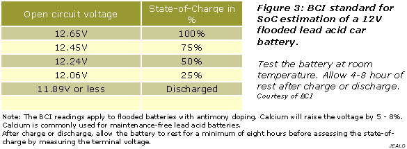
12V Flooded Lead Acid Car Battery.PNG
12.04 KB


Audioguru,
Using a 12V Flooded Lead Acid Car Battery or any 12V battery,
which o/p voltage of the battery to be consider in designing a Ckt. ?
...I mean the battery reaches 13.8V- 13.5V when charged but its nominal voltage is 12.65V (according to the table @ Battery university) when the load is not connected?
So, does it mean that in my Ckt. here I must consider the supply voltage as 12V not 13.5V ?


quote:
Originally posted by audioguru

Your 2N3704 transistor has a base current of 0.8mA. Its collector current is 3.2mA.
The 2N3906 transistor has a base current of 3.2mA and a collector current of 16mA.


Download Attachment: 
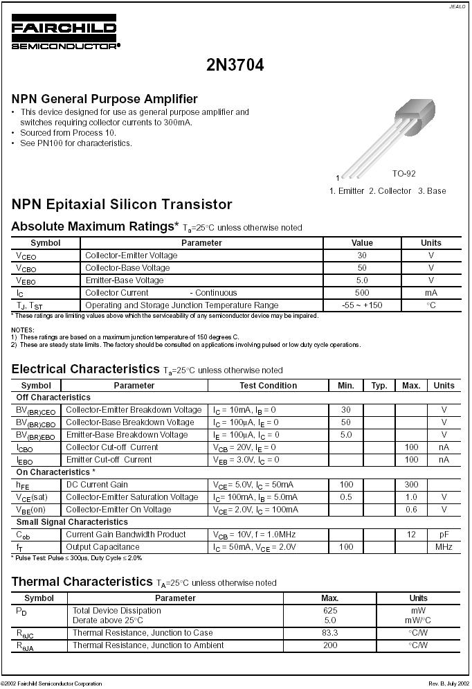
2N3704 NPN_datasheet.PNG
73.34 KB


How come the base current of 2N3906 is 3.2mA which equals also to the collector current of 2N3704 in my Ckt. ?

*I need to increase the o/p current from the 2N3906 to approx. 100mA.

BTW.. Do you think the Zener diode is needed to protect the ICs ( MSW drive Ckt.) from voltage spikes ?


Thank you


juan dela cruz
Penniless INVENTOR
Go to Top of Page

audioguru
Nobel Prize Winner

Canada
4218 Posts

Posted - Sep 05 2008 :  7:30:36 PM  Show Profile  Reply with Quote
Your battery voltage is from 11.9v to 13.8V when it does not have a load (open circuit). Its voltage is less when it drives a loaded inverter.

Ohm's Law determines the current from the 2N3906.

The CD4047 has a max allowed supply voltage of 18V to 22V. Use a 15V or 16V zener diode instead of a 12V one.
Where is 100mA going to go?

Go to Top of Page
Page: of 7 Previous Topic Topic Next Topic  
Previous Page
 New Topic  Reply to Topic
 Printer Friendly
Jump To:
Aaron's Homepage Forum © 1995-2020 AARONCAKE.NET Go To Top Of Page
This page was generated in 0.11 seconds. Snitz Forums 2000