| Author |
 Topic Topic  |
|
kbyrne
Apprentece

USA
14 Posts |
 Posted - Jun 01 2011 : 05:59:56 AM Posted - Jun 01 2011 : 05:59:56 AM


|
 I have a problem that I need help with as a home hobbiest only no school training taken or do I have plans to attend school in the future. I have a problem that I need help with as a home hobbiest only no school training taken or do I have plans to attend school in the future.
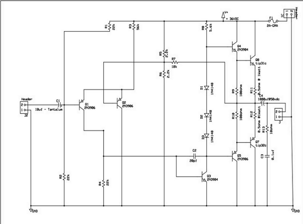
1. Amplifier facts: 12Watt design out of a book by a well known author. Tip 31c & Tip 32c output type design low teck type. Unknown class. Voltage is supposed to be 36vdc @ 2amps.
2. Problems:
A) Humm and is over come by volume.
B) Voltage is supposed to be 36vdc. but is actually 32vdc.
Acording to schematic the power supply is a raw dc type consisting of transformer 24vac @ 2amps, Bridge rectifier and a 1,000uf Filter capacitor. Even with the formula I get 32vdc. output.
Question that I need help with is how do I come up with A raw dc power supply that has the proper dc volts free oh hum for this particular application. I live in the USA and the input voltage is 120vac. thanks |
|
|
audioguru
Nobel Prize Winner

Canada
4218 Posts |
Posted - Jun 01 2011 : 07:11:33 AM
|
A 24V AC transformer produces a peak voltage of 34V and the rectifier bridge charges the filter capacitor to 32V if the capacitor value is high enough and the load is at the max rating of the transformer. 1000uf is fairly small for a current of 2A so there will be plenty of ripple.
Most power amps draw a low current when not playing loudly then the ripple (hum) is low. Most audio amps ignore hum on a simple power supply.
A 36V power supply will power an ordinary amplifier to produce about 15W into 8 ohms. With 32V, an ordinary amp will produce about 11.4W into 8 ohms.
Our hearing's sensitivity to loudness is logarithmic so 11.4W will sound the same as 15W. 7.5W will sound slightly less loud as 15W.
Post the amplifier's schematic so we can see why it is sensitive to power supply hum then change the 1000uF filter capacitor value to 4700uF. |
 |
|
|
Aaron Cake
Administrator

Canada
6718 Posts |
Posted - Jun 01 2011 : 11:08:23 AM


|
| Additionally, cicuit layout can be a major issue. If you have built the circuit on a perf board and routed your supply wires anywhere near or in parallel to your circuit's input, that may be an additional source of hum. If you must route audio carrying wires near power wires before the filtering, then they must only cross and never run along side. |
|
|
|
kbyrne
Apprentece
USA
14 Posts |
|
|
Aaron Cake
Administrator
Canada
6718 Posts |
Posted - Jun 11 2011 : 11:00:05 AM
|
| Hit "Reply To Topic" and on the full reply page, there is a link to "Insert an Image File". Clicking on that link opens up a popup from which you can upload a file up to 250KB. Check the "Show in post" button to have it inserted as an image instead of just a link. |
|
|
|
kbyrne
Apprentece
USA
14 Posts |
Posted - Jul 29 2011 : 11:20:46 AM
|
| I have a (20.1KB) GIF file in Microsoft Paint. Woh con I link up to your site from a E-Mail type set up in Paint to post the schematic Called 12Watt....GIF(20.1KB) I need assistance as this will be my first attempt at trying this out with my computer. tanks |
|
|
|
audioguru
Nobel Prize Winner
Canada
4218 Posts |
Posted - Jul 29 2011 : 3:05:41 PM
|
Use Reply To Topic to make your reply, not Quick Reply.
Under the window is a link to Insert An Image File, click on it.
Click on Browse then find the file in your computer and click on it.
Tick the box for Show An Image In Post.
Click on Upload To Your Post.
Post the reply.
Then we can see your schematic.
Did you use shielded audio cable to connect the music source to the input of this amplifier? |
|
|
|
Aaron Cake
Administrator
Canada
6718 Posts |
Posted - Jul 30 2011 : 10:49:22 AM
|
quote:
Originally posted by kbyrne
I have a (20.1KB) GIF file in Microsoft Paint. Woh con I link up to your site from a E-Mail type set up in Paint to post the schematic Called 12Watt....GIF(20.1KB) I need assistance as this will be my first attempt at trying this out with my computer. tanks
As mentioned, use the "Reply To Topic" link. Below the area for typing your message, there is a link to "Insert an Image File". Click it. A popup appears (you may need to allow the site in you popup blocker). Browse to the file, choose whether to insert it as an image or just a link, then hit the "Upload button". |
|
|
|
rider21
Apprentece
Philippines
8 Posts |
Posted - Aug 29 2011 : 02:04:18 AM
|
hi...gud day to all electronics enthusiasts AND EXPERTS...
i need some help...can anyone pls help me what transistor can i use as a CURRENT amplifier...i need a high current gain...pls give me some transistor name...2N___???..I NEED 2 AMPLIFY A 200ma supply current into some 500ma...pls help...thank you..
|
|
|
|
audioguru
Nobel Prize Winner
Canada
4218 Posts |
Posted - Aug 29 2011 : 8:52:54 PM
|
Yopu cannot "amplify" the max output current of a power supply.
Instead you must use a power supply that produces the amount of current that you need. |
|
|
|
Aaron Cake
Administrator
Canada
6718 Posts |
Posted - Sep 03 2011 : 10:14:35 AM
|
Well, you could by dropping the voltage down, but I doubt that's what you want to do.  |
|
|
|
kbyrne
Apprentece
USA
14 Posts |
|
|
kbyrne
Apprentece
USA
14 Posts |
Posted - Jan 27 2012 : 07:34:09 AM
|
| Hi Guys. I finally was able to figure out how to upload to your site successfully. Voltage to completed two boards is 36.0 and ground. Each amplifier board is independent of each other. Both grounds travel independently to two power supply boards. What I have is a plastic box with amplifiers that work and produce a small amount of hum. That is the reason for this post. Thank you for all advise thou. P.S. There are two transformers also for the two power supply boards. |
|
|
|
audioguru
Nobel Prize Winner
Canada
4218 Posts |
Posted - Jan 28 2012 : 5:39:47 PM
|
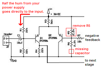
Of course your amplifier produces hum.
The power supply has hum and since R1 is not fed from an RC filter then half the hum on the power supply goes directly into the input.
R1 should be fed from a 1k series resistor from +36V and a 100uF capacitor to ground.
Download Attachment:  amplifier input.PNG amplifier input.PNG
27.87 KB
 |
|
|
|
kbyrne
Apprentece
USA
14 Posts |
Posted - Jan 29 2012 : 10:51:36 AM
|
| Hi guys: If I redo the amplifier board like you said because another author talked about the RC filter what should the missing capacitor value be? |
|
|
|
audioguru
Nobel Prize Winner
Canada
4218 Posts |
Posted - Jan 29 2012 : 11:02:33 AM
|
In my reply I said to make a filter with a 1k series resistor and a 100uF capacitor to ground. Then the hum is reduced 75 times (about -37dB).
If you want less hum then increase the capacitor value. |
|
|
|
Topic |
|
 ScreenHunter_01 Jan. 27 07.01.png