| Author |
 Topic Topic  |
|
Saso
New Member
Slovenia
3 Posts |
|
|
audioguru
Nobel Prize Winner

Canada
4218 Posts |
 Posted - Jun 03 2008 : 10:31:58 PM Posted - Jun 03 2008 : 10:31:58 PM


|
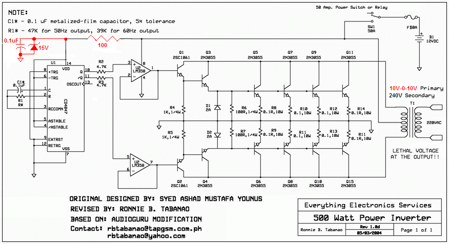
The 500W inverter circuit is simple and produces a square-wave. Many electronic products won't operate properly from a square-wave inverter.
The CD4047 IC also needs a bypass capacitor like this:
Download Attachment:  500W inverter smalll pic.PNG 500W inverter smalll pic.PNG
160.81 KB
 |
 |
|
|
Saso
New Member
Slovenia
3 Posts |
Posted - Jun 04 2008 : 04:02:28 AM
|
Audioguru, thanks. It works.
I have one more question. If there is no load at output the voltage is 150V. If I connect the load, the voltage drops. If the load draws 0,07A the voltage is 100V and if the load draws 1A the voltage drops to 75V. Is that normal? Can I prevent that?
Saso |
|
|
|
audioguru
Nobel Prize Winner
Canada
4218 Posts |
Posted - Jun 04 2008 : 12:01:56 PM
|
The output is a square-wave that must be measured with an oscilloscope or a "True-RMS" meter.
The battery must be a huge lead-acid one from a big car or a "deep discharge" one from a motor home.
Then when the battery is fully charged at 13.2V the square-wave output will be about 130VAC RMS without a load and about 106VAC RMS with a 500W load. The transformer should be 10V-0V-10V to 120V. |
|
|
|
kivdenn
Nobel Prize Winner
Uganda
535 Posts |
Posted - Jun 09 2008 : 03:37:03 AM
|
Hey Juan why did you opt for this and left the one that used the CD4047 and CD4025 ICs that produced a modified sine wave output?
Thanks |
|
|
|
pebe
Nobel Prize Winner
United Kingdom
1078 Posts |
Posted - Jun 09 2008 : 08:15:34 AM
|
Juan,
There is a mistake on your wiring diagram!
The cathodes of D3 and D4 should go to CE (pin13) NOT to ground. Wiring the way you have them will cause them, or the 4017, to pop! Your earlier circuit showed them wired correctly. |
|
|
|
JUAN DELA CRUZ
Mad Scientist

Philippines
476 Posts |
Posted - Jun 10 2008 : 04:14:14 AM
|
To Kivdenn:
> This modified-sine inverter is
better than MSW inverter w/ CD4047 and CD4025 ICs. For the reason that this MSW inverter has a 'stable voltage output'.
To Mr. Pebe:
> Ooops! Sorry about that. I'll fix it.
HERE IS THE EDITED DIAGRAM:
D3 & D4 IS CONNECTED TO PIN 13 & R9 & C7
(CIRCUIT WHERE REMOVED DUE TO TECHNICAL REASON) |
juan dela cruz
Penniless INVENTOR |
Edited by - JUAN DELA CRUZ on Sep 17 2008 09:39:18 AM |
|
|
|
audioguru
Nobel Prize Winner
Canada
4218 Posts |
Posted - Jun 10 2008 : 11:39:28 AM
|
Now the schematic is confusing.
D3 and D4 connect to pin 5-and-a-half on the CD4017.
EDIT:
Thanks again Juan for fixing the schematic. |
Edited by - audioguru on Jun 10 2008 11:24:59 PM |
|
|
|
kivdenn
Nobel Prize Winner
Uganda
535 Posts |
Posted - Jun 11 2008 : 10:23:19 AM
|
So what do you mean? is the circuit OK or NOT? Thanks
Dennis |
|
|
|
audioguru
Nobel Prize Winner
Canada
4218 Posts |
Posted - Jun 11 2008 : 12:03:54 PM
|
quote:
Originally posted by kivdenn
So what do you mean? is the circuit OK or NOT? Thanks
Dennis
Juan corrected the errors on his schematic so it should be fine. |
|
|
|
kivdenn
Nobel Prize Winner
Uganda
535 Posts |
Posted - Jun 14 2008 : 03:04:13 AM
|
| How can I modify this for 24V and 48V battery outputs |
|
|
|
audioguru
Nobel Prize Winner
Canada
4218 Posts |
Posted - Jun 14 2008 : 3:36:41 PM
|
| Juan's circuit can be completely re-designed to work from 24V or 48V. |
|
|
|
JUAN DELA CRUZ
Mad Scientist
Philippines
476 Posts |
Posted - Jun 15 2008 : 01:46:47 AM
|
quote:
Originally posted by kivdenn
How can I modify this for 24V and 48V battery outputs
Hi Dennis...
Why will you need to modify the MS-wave inverter for 24V/48V???
.......to increase the output of the MS-wave inverter???
I think you just 'arrange your battery bank in parallel' (add a Power mosfets or just use better mosfet likewise change your Xformer to handle huge current) to increase the output of the MS-wave inverter.
Hope it helps you.... |
juan dela cruz
Penniless INVENTOR |
Edited by - JUAN DELA CRUZ on Jun 15 2008 02:09:13 AM |
|
|
|
kivdenn
Nobel Prize Winner
Uganda
535 Posts |
Posted - Jun 16 2008 : 07:02:37 AM
|
quote:
Originally posted by audioguru
Juan's circuit can be completely re-designed to work from 24V or 48V.
Please help me and show me how to do it because I have always tried to do it but the fets blow on each power on. thanks |
|
|
|
steven
New Member
China
1 Posts |
Posted - Jun 17 2008 : 11:46:22 AM
|
| hi,i have a question wanna to ask upstairs,what's the friquency(it seems only 0.5Hz)?what do you wanna to use for? your input fuse is 5A,but your switching transistor is 3055*2? How many Watt do u wanna to output? i am engineer for power supply, i think i can help u to complet this case. |
|
|
|
Topic |
|