| Author |
 Topic Topic  |
|
kivdenn
Nobel Prize Winner
    
Uganda
535 Posts |
 Posted - Feb 19 2009 : 01:55:33 AM Posted - Feb 19 2009 : 01:55:33 AM


|
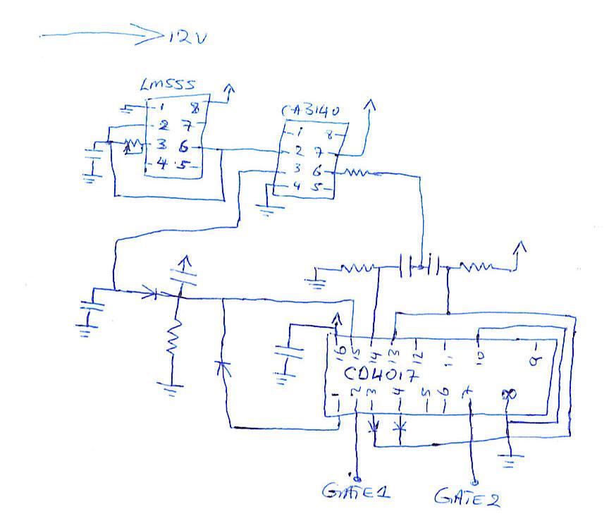
Hey all, I have analysed this circuit http://www.aaroncake.net/forum/uploaded/JUAN%20DELA%20CRUZ/200861173754_LOW%20COST%20500W%20MODIFIED%20SINE%20WAVE%20INVERTER.GIF and realised the the LVD circuit is makin it very user unfriendly as the user has to manualy turn it on when the the LVD is activated and the battery has regained. It is for this reason that I want to eliminate the LVD circuit and replace it with my window voltage comparator that automaticaly off and on and the battery discharges and recharges. I have tried to modify the circuit and this is waht i have come up with , is it ik? Thanks Dennis
Download Attachment:  Oscilator1.jpg Oscilator1.jpg
53.82 KB
 |
Edited by - kivdenn on Feb 19 2009 01:57:54 AM |
|
|
pebe
Nobel Prize Winner
    
United Kingdom
1078 Posts |
 Posted - Feb 19 2009 : 04:36:49 AM Posted - Feb 19 2009 : 04:36:49 AM


|
| At what battery voltage or state-of-charge do you want the inverter to come back on? |
 |
|
|
kivdenn
Nobel Prize Winner
    
Uganda
535 Posts |
 Posted - Feb 20 2009 : 02:14:03 AM Posted - Feb 20 2009 : 02:14:03 AM


|
I want the automatic LVD circuit to shutdown at 10.5 and reconect and reconnect at 11.5 hence a window voltage of 1 volt. I dont want one with a reset button.
By the way can my circuit above work after I eliminated the LVD circuit? Thanks
Dennis |
 |
|
|
pebe
Nobel Prize Winner
    
United Kingdom
1078 Posts |
 Posted - Feb 20 2009 : 04:22:03 AM Posted - Feb 20 2009 : 04:22:03 AM


|
quote:
Originally posted by kivdenn
I want the automatic LVD circuit to shutdown at 10.5 and reconect and reconnect at 11.5 hence a window voltage of 1 volt. I dont want one with a reset button.
The battery voltage might rise above 11.5volts once the load is removed, so defeating the object. But why have you got an objection to the reset button? Are you using the inverter to supply electricity when the public utility's electricity fails? And do you to charge the battery from it? If so, you will have to have a means of disconnecting your inverter from the load when the supply comes back on. Why not incorporate thye reset with that?
quote:
By the way can my circuit above work after I eliminated the LVD circuit? Thanks
Dennis
How I HATE trying to decypher wiring diagrams that only show pin numbers, and not the functions of an IC.
As far as I can see, you have no way of measuring the battery voltage, so it won't work. |
 |
|
|
kivdenn
Nobel Prize Winner
    
Uganda
535 Posts |
 Posted - Mar 02 2009 : 10:11:50 AM Posted - Mar 02 2009 : 10:11:50 AM


|
quote:
Originally posted by pebe
At what battery voltage or state-of-charge do you want the inverter to come back on?
Can this circuit work minus it LVD circuit? Thanks |
 |
|
|
pebe
Nobel Prize Winner
    
United Kingdom
1078 Posts |
|
|
kivdenn
Nobel Prize Winner
    
Uganda
535 Posts |
 Posted - Mar 04 2009 : 11:14:33 AM Posted - Mar 04 2009 : 11:14:33 AM


|
| What kind of wave do you think this oscilator will produce? It looks like it produces a square wave, am I right? thanks |
 |
|
|
pebe
Nobel Prize Winner
    
United Kingdom
1078 Posts |
 Posted - Mar 04 2009 : 12:21:00 PM Posted - Mar 04 2009 : 12:21:00 PM


|
| The waveforms are shown on the main circuit in red. |
 |
|
|
audioguru
Nobel Prize Winner
    
Canada
4218 Posts |
 Posted - Mar 04 2009 : 4:55:46 PM Posted - Mar 04 2009 : 4:55:46 PM


|
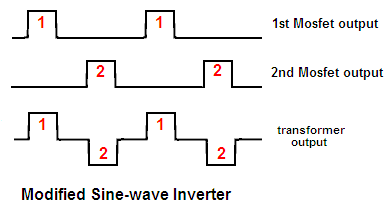
A modified sine-wave inverter also has a modified square-wave.
There is a pause of 0V in between each AC swing. The AC swing has almost the same peak voltage as a sine-wave.
Download Attachment:  modified sine-wave inverter waveforms.PNG modified sine-wave inverter waveforms.PNG
6.48 KB
 |
 |
|
|
kivdenn
Nobel Prize Winner
    
Uganda
535 Posts |
 Posted - Mar 05 2009 : 06:31:38 AM Posted - Mar 05 2009 : 06:31:38 AM


|
quote:
Originally posted by pebe
If you are talking about the circuit in your first posting then yes, it will.
Here is the original.
http://www.aaroncake.net/forum/topic.asp?TOPIC_ID=7531&whichpage=2
But NOTE that CE and CK of the 4017 are shown THE WRONG WAY ROUND!
Am sorry to ask, but what do you mean by CE and CK and how have I wrongly drawm them because I drew this from the original circuit, could you please help me correct them? Thanks
Dennis |
 |
|
|
wasssup1990
Nobel Prize Winner
    
A Land Down Under
2261 Posts |
 Posted - Mar 05 2009 : 06:32:45 AM Posted - Mar 05 2009 : 06:32:45 AM


|
CE = Clock Enable
CK = Clock |
When one person suffers from a delusion it is called insanity.
When many people suffer from a delusion it is called religion. |
 |
|
|
pebe
Nobel Prize Winner
    
United Kingdom
1078 Posts |
 Posted - Mar 05 2009 : 09:25:54 AM Posted - Mar 05 2009 : 09:25:54 AM


|
quote:
Originally posted by kivdenn
quote:
Originally posted by pebe
If you are talking about the circuit in your first posting then yes, it will.
Here is the original.
http://www.aaroncake.net/forum/topic.asp?TOPIC_ID=7531&whichpage=2
But NOTE that CE and CK of the 4017 are shown THE WRONG WAY ROUND!
Am sorry to ask, but what do you mean by CE and CK and how have I wrongly drawm them because I drew this from the original circuit, could you please help me correct them? Thanks
Dennis
In the original circuit had CE and CK labelled for the wrong pins. It wasn't you who had wrongly drawn them - it was me. |
 |
|
|
kivdenn
Nobel Prize Winner
    
Uganda
535 Posts |
 Posted - Mar 06 2009 : 05:09:55 AM Posted - Mar 06 2009 : 05:09:55 AM


|
How do I correct them then? Thanks
Dennis |
 |
|
|
pebe
Nobel Prize Winner
    
United Kingdom
1078 Posts |
 Posted - Mar 06 2009 : 07:36:54 AM Posted - Mar 06 2009 : 07:36:54 AM


|
You simply change over the labels on the circuit!
CK should connect to R7 and CE should connect to R8 |
 |
|
|
kivdenn
Nobel Prize Winner
    
Uganda
535 Posts |
 Posted - Mar 07 2009 : 04:49:10 AM Posted - Mar 07 2009 : 04:49:10 AM


|
What are the pin numbers for CK and CE? Thanks
Dennis |
 |
|
|
pebe
Nobel Prize Winner
    
United Kingdom
1078 Posts |
|
 Topic Topic  |
|

