| Author |
 Topic Topic  |
|
kivdenn
Nobel Prize Winner
    
Uganda
535 Posts |
 Posted - Mar 08 2009 : 11:00:21 AM Posted - Mar 08 2009 : 11:00:21 AM


|
| Please redraw the circuit for me. Am new to this.Thanks Dennis |
 |
|
|
pebe
Nobel Prize Winner
    
United Kingdom
1078 Posts |
 Posted - Mar 08 2009 : 11:50:24 AM Posted - Mar 08 2009 : 11:50:24 AM


|
quote:
Originally posted by kivdenn
Please redraw the circuit for me. Am new to this.Thanks Dennis
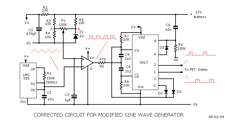
Here is the amended circuit.
Download Attachment:  Modified Sine Wave 2.GIF Modified Sine Wave 2.GIF
10.32 KB
 |
 |
|
|
kivdenn
Nobel Prize Winner
    
Uganda
535 Posts |
 Posted - Mar 13 2009 : 08:40:13 AM Posted - Mar 13 2009 : 08:40:13 AM


|
The battery voltage might rise above 11.5volts once the load is removed, so defeating the object. But why have you got an objection to the reset button? Are you using the inverter to supply electricity when the public utility's electricity fails? And do you to charge the battery from it? If so, you will have to have a means of disconnecting your inverter from the load when the supply comes back on. Why not incorporate thye reset with that?
Yes I am making that kind of inverter and so far I have been successfull but the only problem is the automaic low battery disconnect circuit, I dont want to use the one with a resset switch because then it becomes manual yet I want this to be automatic.
Please help me remove the resset switch in your circuit or correct my LVD circuit in the other thread. Thanks
Dennis |
 |
|
|
kivdenn
Nobel Prize Winner
    
Uganda
535 Posts |
 Posted - Mar 13 2009 : 08:57:08 AM Posted - Mar 13 2009 : 08:57:08 AM


|
quote:
Originally posted by pebe
quote:
Originally posted by kivdenn
Please redraw the circuit for me. Am new to this.Thanks Dennis
Here is the amended circuit.
Download Attachment:  Modified Sine Wave 2.GIF Modified Sine Wave 2.GIF
10.32 KB

Let me hope CK is pin 14,CE is pin 13 and R is pin 15. I have no idea on what pin 0 is,this is where the anode of diode D2 is connected. Please clarify this to me. Thanks
Dennis |
 |
|
|
pebe
Nobel Prize Winner
    
United Kingdom
1078 Posts |
 Posted - Mar 13 2009 : 09:35:56 AM Posted - Mar 13 2009 : 09:35:56 AM


|
| Output '0' means 'Q0'. It is one of the outputs of the chip (there are 10 outputs, Q0 to Q9) |
 |
|
|
kivdenn
Nobel Prize Winner
    
Uganda
535 Posts |
 Posted - Mar 16 2009 : 01:58:26 AM Posted - Mar 16 2009 : 01:58:26 AM


|
I would like to put a low current on/off switch, should I put this between the battery B+ and the circuit? Thanks
Dennis |
 |
|
|
pebe
Nobel Prize Winner
    
United Kingdom
1078 Posts |
 Posted - Mar 16 2009 : 03:43:28 AM Posted - Mar 16 2009 : 03:43:28 AM


|
| That's one way. A better way is to take the 4017 Reset pin high. |
 |
|
|
kivdenn
Nobel Prize Winner
    
Uganda
535 Posts |
 Posted - Mar 17 2009 : 02:30:34 AM Posted - Mar 17 2009 : 02:30:34 AM


|
I think that is doen by connecting a 100k resistor to pin 15 and the Bat+. Am I correct? Thanks
Dennis |
 |
|
|
pebe
Nobel Prize Winner
    
United Kingdom
1078 Posts |
 Posted - Mar 17 2009 : 03:22:01 AM Posted - Mar 17 2009 : 03:22:01 AM


|
No, taking pin15 to +V through a 100K will give half batt+ (6V) at the pin. That is not enough to reset the 4017.
You need to take the pin direct to batt+. |
 |
|
|
kivdenn
Nobel Prize Winner
    
Uganda
535 Posts |
 Posted - Mar 19 2009 : 06:59:42 AM Posted - Mar 19 2009 : 06:59:42 AM


|
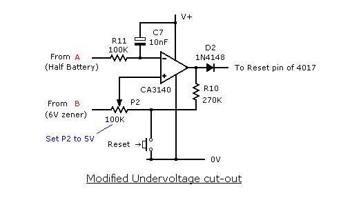
It seems I have completely failed to make an LVD circuit, can you guys help me remove the reset burton from this circuit and replace it with hysterisis controlled automation. Thanks
Dennis
Download Attachment:  Undervolt cut.gif Undervolt cut.gif
4.51 KB
 |
Edited by - kivdenn on Mar 19 2009 07:01:13 AM |
 |
|
|
pebe
Nobel Prize Winner
    
United Kingdom
1078 Posts |
 Posted - Mar 19 2009 : 12:12:13 PM Posted - Mar 19 2009 : 12:12:13 PM


|
Kivdenn,
Go back to page 1 of this thread.
Then read and digest my posting of Feb 20.
|
 |
|
|
kivdenn
Nobel Prize Winner
    
Uganda
535 Posts |
 Posted - Mar 23 2009 : 11:00:24 AM Posted - Mar 23 2009 : 11:00:24 AM


|
quote:
Originally posted by pebe
quote:
Originally posted by kivdenn
I want the automatic LVD circuit to shutdown at 10.5 and reconect and reconnect at 11.5 hence a window voltage of 1 volt. I dont want one with a reset button.
The battery voltage might rise above 11.5volts once the load is removed, so defeating the object. But why have you got an objection to the reset button? Are you using the inverter to supply electricity when the public utility's electricity fails? And do you to charge the battery from it? If so, you will have to have a means of disconnecting your inverter from the load when the supply comes back on. Why not incorporate thye reset with that?
quote:
By the way can my circuit above work after I eliminated the LVD circuit? Thanks
Dennis
How I HATE trying to decypher wiring diagrams that only show pin numbers, and not the functions of an IC.
As far as I can see, you have no way of measuring the battery voltage, so it won't work.
Yes I am making an automatic DC-AC inverter charger and would like to include an automatic LVD circuit without a resset burton. Yo post on 20th feb says nothing about removing the reset burton. could you please help me with this. Thanks.
Dennis |
 |
|
|
kivdenn
Nobel Prize Winner
    
Uganda
535 Posts |
 Posted - Mar 23 2009 : 11:05:24 AM Posted - Mar 23 2009 : 11:05:24 AM


|
Yes I am making an automatic DC-AC inverter charger and would like to include an automatic LVD circuit without a resset burton. Yo post on 20th feb says nothing about removing the reset burton. could you please help me with this. Thanks.
Dennis |
 |
|
|
pebe
Nobel Prize Winner
    
United Kingdom
1078 Posts |
 Posted - Mar 23 2009 : 11:33:54 AM Posted - Mar 23 2009 : 11:33:54 AM


|
quote:
Originally posted by kivdenn
Yes I am making an automatic DC-AC inverter charger and would like to include an automatic LVD circuit without a resset burton. Yo post on 20th feb says nothing about removing the reset burton. could you please help me with this. Thanks.
Dennis
My post said this:
quote:
The battery voltage might rise above 11.5volts once the load is removed, so defeating the object. But why have you got an objection to the reset button? Are you using the inverter to supply electricity when the public utility's electricity fails? And do you to charge the battery from it? If so, you will have to have a means of disconnecting your inverter from the load when the supply comes back on. Why not incorporate thye reset with that?
I asked 3 questions. You have not answered any of those questions.
So let me try to put it another way.
1. You are running the inverter and the battery goes flat, so the LVD cuts off the inverter.
2. If you had an auto-resetting LVD, the inverter would not come on again till the battery was charged up to auto-reset the LVD.
3. So what makes the battery automatically charge?
Think about it. Then tell me the sequence of events from the time the LVD cuts off the battery, to the time when the battery is fully charged again. Then perhaps there may be a solution. |
 |
|
|
kivdenn
Nobel Prize Winner
    
Uganda
535 Posts |
 Posted - Mar 24 2009 : 05:19:13 AM Posted - Mar 24 2009 : 05:19:13 AM


|
Ok this is what happens, In my inverter I use one transformer which is used for charging and inverting. Both events are controlled by a four way relay switch powered by the grid power through a second small transformer about 200ma. When grid power disapears, this relay switch togles and its first way switches on the oscilator and inversion is activated. During this time the battery volatge will fall to a low level of 10.5V and the LVD will activated.
When grid power re-apears the relay switch will be powered through the 200ma transformer and it togles again. The second way of this relay switch will now feeds AC power to a three windings transformer (8V-0-8V,16V and 230V)and the first way will now switch off the oscilator to avoid blowing of the fets when the transformer is powered. Now battery charging is activated. It is the 16V winding of the transormer that is used to charge the battery ofcourse controled by a charge control circutry.When the battery voltage reaches 12V the LVD circuit should reconnect. Remember this LVD circuit is in series with the first way of the relay switch so even if the LVD reconnects, the oscilator will not get on until grid power fails again this is done to avoid blowing of the fets.The third way of the relay switch simply togles between inverter and grid live terminals as the neutrals are already connected together.
The fourth way controls the charge control circuitry so that there is no charging during the inverter mode. |
 |
|
 Topic Topic  |
|

