| Author |
 Topic Topic  |
|
|
Aaron Cake
Administrator

Canada
6718 Posts |
 Posted - Oct 13 2005 : 09:15:40 AM Posted - Oct 13 2005 : 09:15:40 AM


|
Its that time again. Yes, time for another installment of my ongoing turbo-NA-bridgeport project. As always, things have been progressing. Sometimes slowly, sometimes quickly. Quite a bit of work has been done since the last update, which can be found here. Without further rambling, let's just get to the interesting stuff.
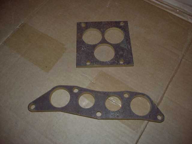
When we last left off, my intake and throttle body flanges had just come back from being made. The machine shop cut them on a water jet machine from the CAD drawings I sent it. I will be certainly using the intake flange, but the throttle body flanges will not be used. There's nothing wrong with them, I just have no need...but details on that will come later.
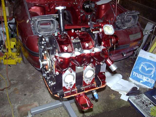
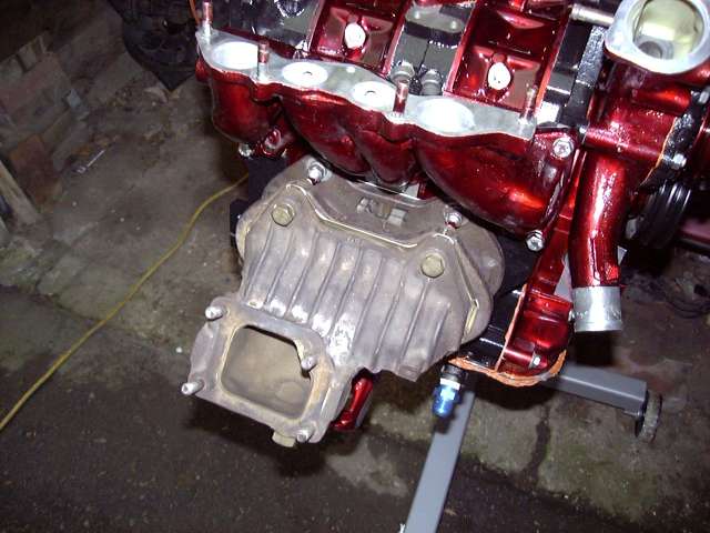
It's time to prepare to reinstall the engine. First steps are to install the lower intake, water pump housing, and water pump. Nothing special here. New gaskets were used, as well as all stainless hardware. Notice that the water pump housing has NOT been tapped for an aftermarket temp gauge. At that point, I had not decided which gauge to use. The decision has since been made, so it will be a bit of a pain to drill and tap while on the car. At least the cast aluminum is soft.
After the water pump was mounted, the eccentric and water pump pulleys were installed. These are rotating parts, so blue Loctite was used on all (stainless steel) bolts.
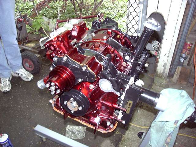
Now time for the turbo manifold. Anti-seize was applied to the threads, then the exhaust spacer and manifold were bolted in place. As I have mentioned before, the stock turbo is only being used for breakin, so the stock turbo components have not been cleaned up and painted.
It was then time to bolt on the turbocharger. Notice the copper locknuts. A major problem with most TIIs is that the turbo nuts loosen up over time. From the factory, they're fine. But once removed and reinstalled, they always seem to loosen again. These copper nuts are available from [url=http://www.atpturbo.com]ATP Turbo[/url] for about $1 each. Being made of soft copper they really grip the stud. There is also a locking ring above the main threaded portion. Once tightened they WILL NOT LOOSEN up without great effort. One thing to keep in mind if you use these is that when torquing them down, the nuts must be gripped on all sides. If you use an open ended wrench they will simply round off.
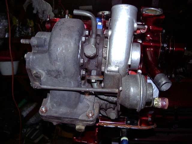
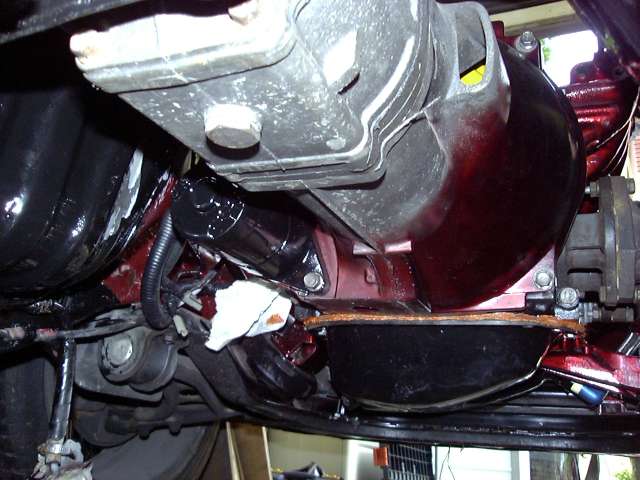
Once the turbo was solidly mounted the controversial oil drain hose was installed. However, it would not remain attached for very long.
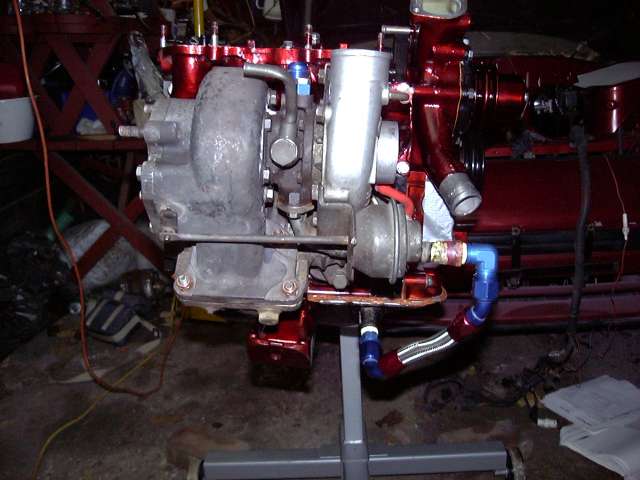
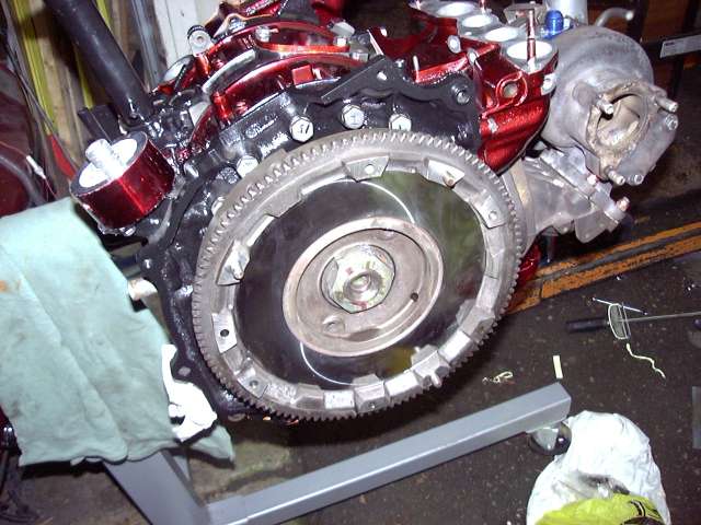
Finally, the flywheel was mounted. The oil seal was coated with assembly lube, the flywheel key inserted, and then the flywheel itself slipped over the shaft. When torquing the nut, the "crude" method was used. It was snugged up by hand, then banged on with the impact gun until it wouldn't turn any more. At this point I was going to install the clutch, but found that the flywheel had damaged threads due to...um....me trying to hammer one of the dowels into the wrong hole. As I didn't have the correct tap for the threads, the clutch would have to be installed later.
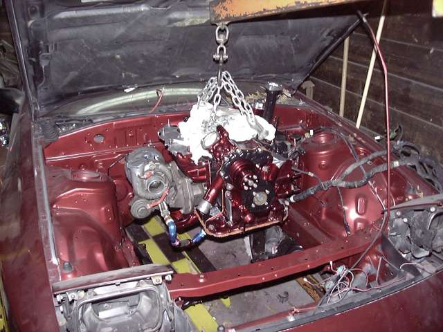
Almost time. The engine was hung from the hoist in preparation for installation. Until now you may not have noticed that it was raining that day. Actually, it was pouring. Earlier in the day I had to erect a temporary shelter at the mouth of the garage to keep out the weather. In general things were kept fairly dry but once and a while the wind would blow some moisture underneath the tarp.
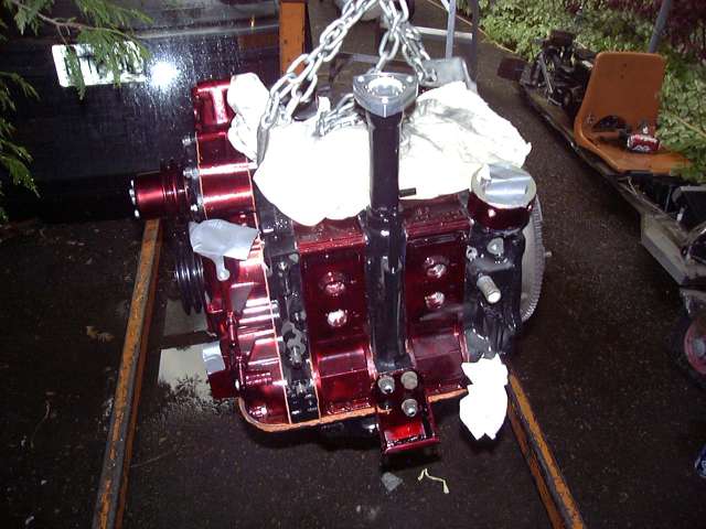
And the engine is being lowered in place.
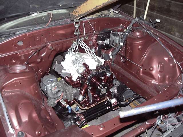
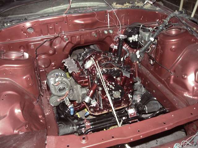
Well there you have it. For the first time in nearly 3 years, the car and engine are once again together. Aside from some frustration with the passenger side engine mount nuts, the process went very smoothly. Note the twine used to prevent the engine from falling backwards. As of yet, no transmission had been mounted to support the rear end.
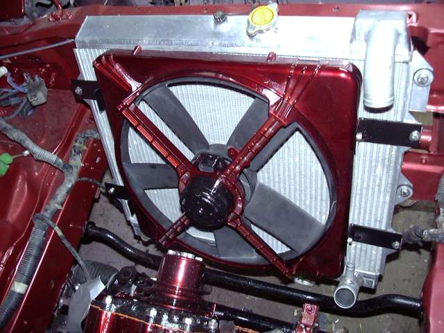
The radiator was then mounted. New rubber bushings were previously ordered from Mazda and of course stainless bolts with plenty of antiseize were used.
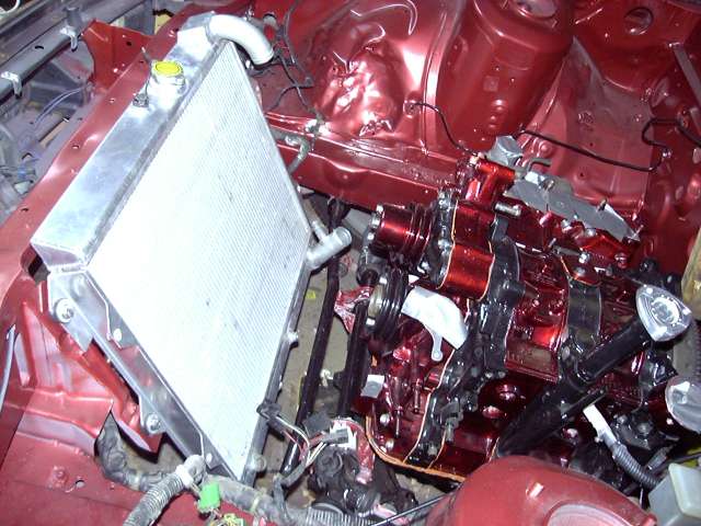
Yes, I run an electric fan. The reason is simply because my clutch fan failed several years ago, and I didn't feel like paying the high cost for replacement. This fan was originally on a Pontiac 6000 but they can be found on many GMs up to about the mid to late '90s. These fans fit the stock rad almost perfectly and have a decent shroud. Even though they seem poorly made, they are quite reliable and a dime a dozen to buy. I disassembled this fan, cleaned everything up, painted the motor black and painted the shroud with MetalCast plastic primer followed by 4 layers of MetalCast red. The brackets were made by simply welding two pieces of 3" steel together and then drilling the appropriate holes. As you can see, they fit the stock shroud mounting locations.
This next picture doesn't seem like much, but it represents a little more then 4 weeks of work. It may also seem unnecessary and odd to those in climates that do not experience snow, so I will explain a little. Along with the previous owners of my car, I am guilty of driving it in the winter, though I have not done so since 2001 and do not plan to ever again. This would not be so much of a problem save for the fact that to melt the ice and snow, copious amounts of salt are spread on the roads. As you may have guessed, salt + moisture + steel = rust. In fact, Southwestern Ontario is known throughout most of Canada as "the rust belt". I'm not saying that my car is rotted, or that it's falling apart at it's seams, but as with many 20 year old cars that were winter driven it did show a few areas of concern. I made the decision that if I was going to clean up the underside, I would do it once, do it right, and be done with it. For years, on many of the automotive lists that I read, I have been hearing about the virtues of [url=http://www.por15.com/]POR-15 Rust Preventative Paint[/url]. Many of the most anal, fickle and obsessed enthusiasts I have ever seen have literally entrusted their most important posession to POR-15. It is one of the few products that I have never heard anything negative about. Because I wanted permanent protection, and was only planning to do this job once, I ordered a gallon can of POR-15, and a gallon of their MetalReady pre-primer.
Let me just say one thing first: This was the worst job I have ever done, and I am an idiot for doing it. On a hot July Sunday, I put the car up on ramps and began preparing the underside for painting. Now, POR-15 does not require a completely stripped surface, and indeed it prefers to bite into rust rather then shiney clean metal. Knowing this, I began stripping the underside of all loose rust flakes, factory undercoating, and the 1/8" coat of dirt and oil that had accumulated over the past 20 years. This entire process took one month of working several hours a day (and 8 hours a day on weekends) to complete. Rust was removed with a wire wheel, wire brush and pocket knife. On a tip from Snrub, I used kerosene to quickly strip the factory undercoating. Everyday, this job left me absolutely filthey. My skin went from pale white to black/rust everytime. It took three attempts to totally clean my hair, and I just started not even bothering to try and wash the clothes. Finally, after 3 weeks of torture, it was basically over. The underside was then degreased and washed until it was SPOTLESS, which took several attempts.
Before POR-15 is applied to a surface, that surface must be etched with a product called MetalReady to prepare it. The metal ready neutralizes existing rust, etches bare metal, and leaves a zinc coating for the POR-15 to adhere to. MetalReady is applied, allowed to sit for 20 minutes or so, then rinsed off. What the instructions don't tell you is that MetalReady's main component is phosphoric acid. So in the process of crawling under the car and thoroughly soaking it with MetalReady, I also thoroughly soaked myself with phosphoric acid. This left me with acid burns over most of my body that took about a week to heal. Aside from the searing pain, half of my face looked like The Phantom Of The Opera, so I had to constantly endure the question "What happened to your face?". To the credit of who wrote the instructions, they do tell the user to wear gloves, which I did.
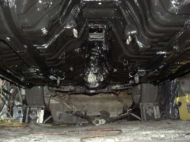
After another week of drying, it was finally time to apply the actual POR-15. On a humid Sunday morning, I began the process. The first coat took several hours to apply, and by the time I was finished I had to immediately start the 2nd coat. I'm not sure that anyone can appreciate how much of a royal pain in the ass painting overhead in a cramped space is. For 6 hours, I contorted my body, slid around on my back, put up with paint drips on my face and sweated my butt off. Finally finishing around 4:30PM, I was literally COVERED HEAD TO TOE in POR-15. Now, the instructions mention that if you get the paint on your skin, nothing will take it off. You better believe they're right. As I was covered in huge amounts of paint, all I could was let it wear off, which took 3 weeks. Imagine that someone had dumped a gallon of black paint on my head, then tripple the amount of paint you are picturing to get an idea of what I looked like.
Would I do it again? Absolutely not. I would rather put a red hot corkscrew in my rectum, twist it slowly and sing hit singles by Britney Spears. But am I happy with the result? Yes, and confident that the hard, slick surface of POR-15 will protect the car for many years.
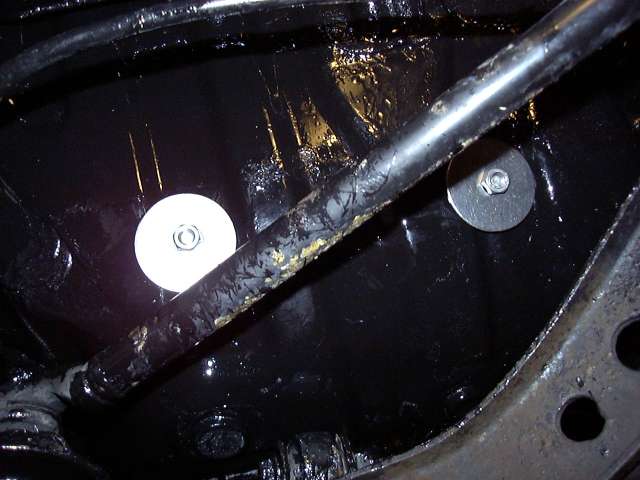
The white areas of the picture below are actually reflections from the camera flash, not flaws in the paint.
Once the underside had cured for a week, it was time to reinstall the transmission. Work doesn't stop just because 85% of your body is sealed in POR-15, you know.
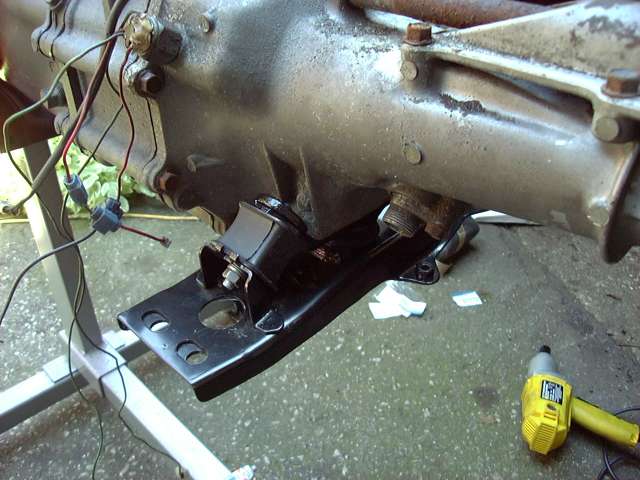
One of the things that had always annoyed me about the car was how mushy and loose the transmission mounts were. This caused the shifter to bounce up and down over bumps and rough roads. The solution is shown here in the form of a brand new transmission crossmember (with lower bushing) and new "competition" side mounts. The second half of my mush-elimination plan is custom shifter that totally eliminates the FC's bushings, but that's another post for another day.
Before the transmission was installed, the clutch of course must be mounted. I quickly used a tap to clean up the flywheel threads, degreased the flywheel surface with brake cleaner, then installed the disc and pressure plate. An alignment tool makes this very easy, but in a pinch a screwdriver can be used. To prevent damage to my new pilot bearing and seal during transmission installation, I made sure that alignment was perfect with the proper tool.
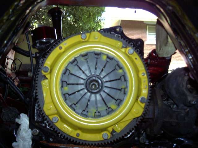
I could swear that I took a picture of the new throughout bearing that I used, but you'll just have to trust me that it's there.
The transmission slid into place fairly easily after some wiggling. The electrical connections were made, and then the starter bolted into place. I clearly cheated and painted only the bellhousing of the transmission. No one in their right mind paints the whole transmission, right? :) That big scar of scrapped paint on the left of the transmission tunnel was caused during installation. The only reason the POR-15 flaked off was because it was an unprepared area where the underlying paint was already weak. Properly applied POR-15 is as hard as powder coat.
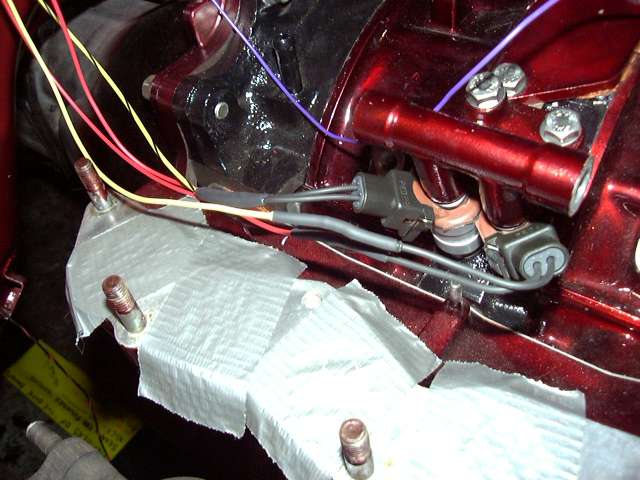
Shown here is the single most expensive part on the entire engine. Well, not really. But if you have to buy one, you will certainly start to think so. This is a brand new primary injector air bleed. I had to lay out $45 for this thing because the original broke during removal.
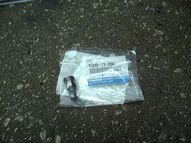
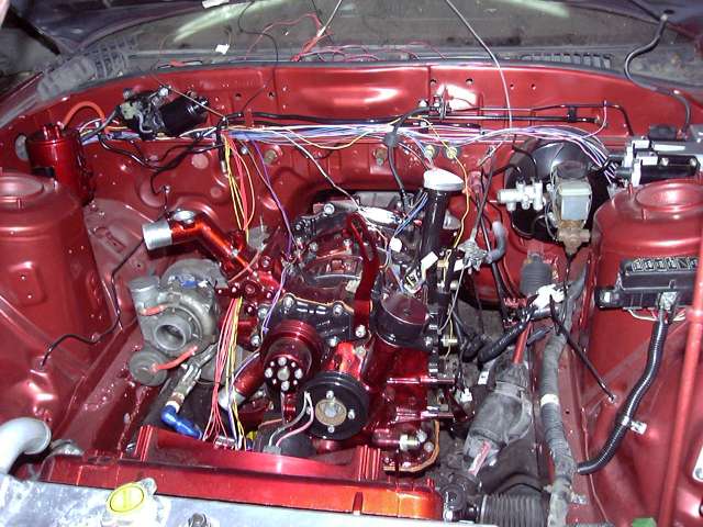
The new primary injector bleed was installed, and new o-rings installed on the remaining old bleed. After that, I began installing some of the other engine components. The CAS, thermostat and water neck, oil fittings, primary injectors and fuel rail and finally the clutch slave cylinder are shown here.
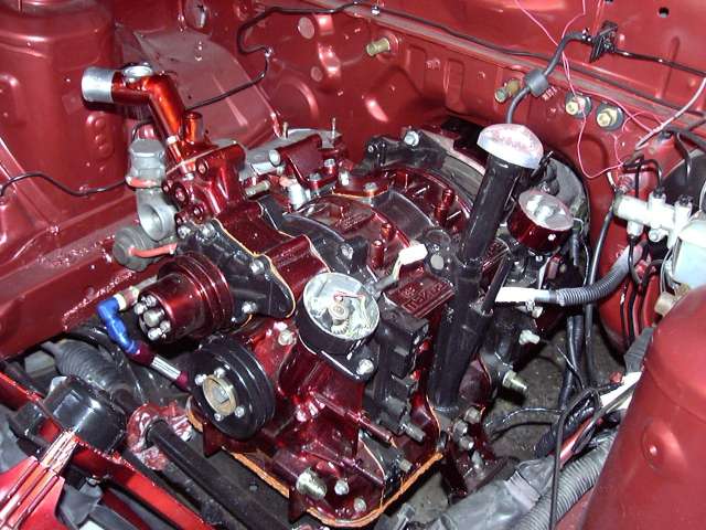
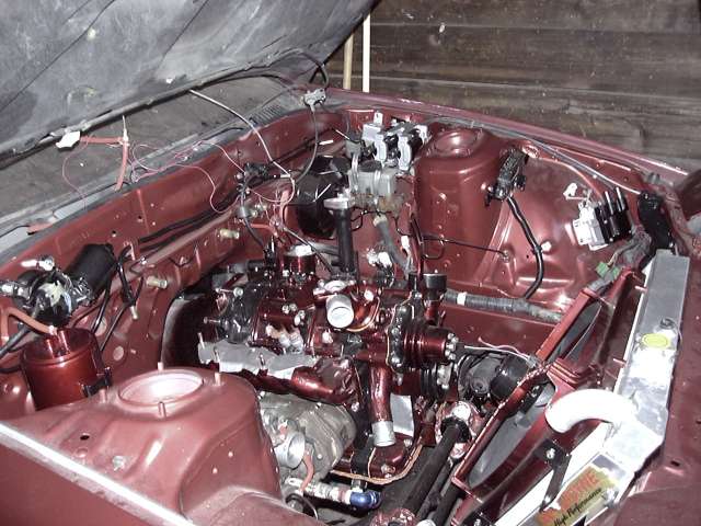
A wider shot, now showing the ignition coils, charcoal canister, wiper motor and fuse panel. The ignition coils were previously disassembled and painted, as was the wiper motor and charcoal canister. Some may wonder why I am keeping the canister. The reason is quite simple actually; I don't want my car to stink like fuel, and there's no good reason not to use it. The original plan was to just paint it black, but I decided to make a statement so it was primed, then sprayed with sliver metal flake, then finally coated with 5 layers of MetalCast red. I will be running stock purge valve to vent both the canister and crankcase. Most of the wiring to the fuse box has been greatly simplified so it fits in a small single harness. The 12V supply wire will eventually come from the passthroughs on the firewall.

Another rather poor image of the engine bay showing the primary injectors and turbo oil drain.
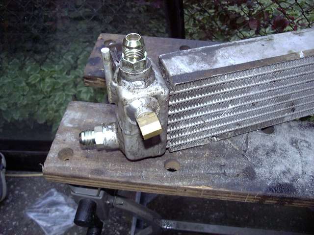
These are the metric to -10 AN fittings for making custom oil cooler lines. New crush washers were used during installation, as well as Teflon sealing compound on the threads. The small 90 degree fitting is a 1/4" elbow for oil supply to the turbo. The appropriate NPT to AN adapter will be added when the time comes.
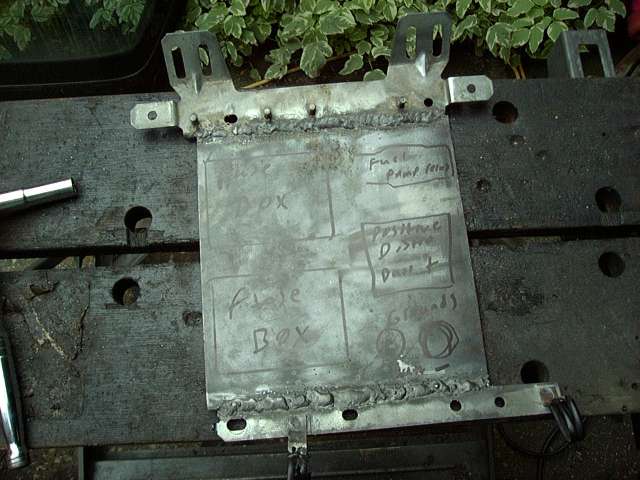
With the installation of the Microtech, the area occupied by the stock ECU becomes free. It seemed like a perfect spot to mount my new electrical panel, so I cut apart the ECU frame and welded in a flat piece of 2MM steel. This would become the base for my new fuse boxes, ground points and +12V distribution block.
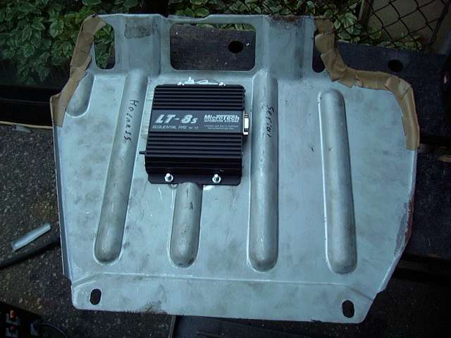
The Microtech LT8s is better then the stock ECU in every conceivable way, including physical size. Thus, I decided to mount my ECU to the underside of the metal ECU cover. Using a jigsaw, I chopped out one of the bulges, then welded in a new flat section of metal. After drilling mounting holes, the ECU was mounted. Clearance is VERY tight between the Microtech and the electrical panel, so I think I will make some 1/4" spacers to move the cover up a little for more room. Still, it's almost as if Mazda had designed the car for what I was doing since everything fits so well. :)
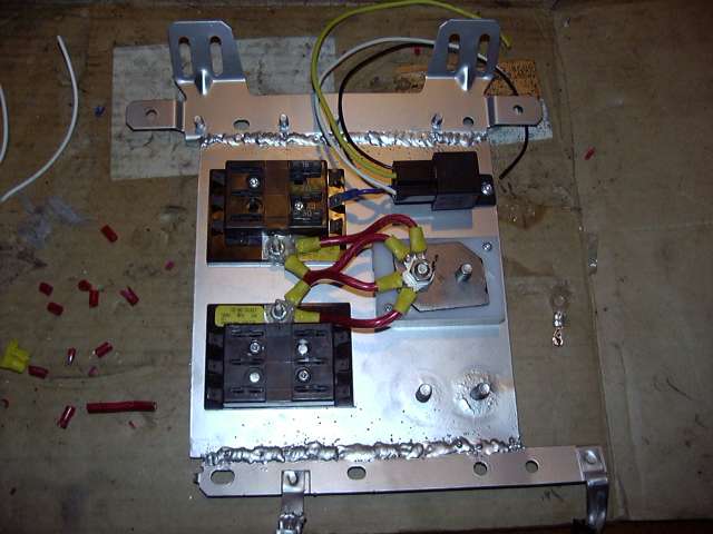
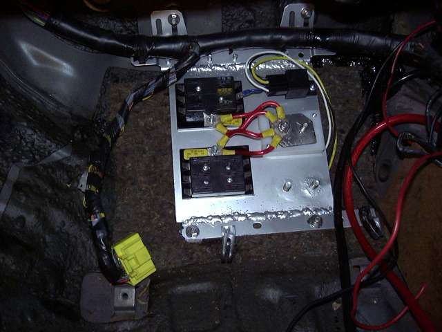
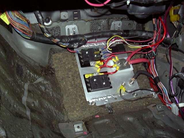
After the panel was cleaned and painted, I laid out the fuse boxes, fuel pump relay and power distribution block. Also notice the two ground studs at the bottom. The power block is something that I made using a block of plastic, two M8 bolts and a little bit of 3MM sheet steel. This was done because I was totally unhappy with the distribution blocks that are available commercially. Most are designed for stereo installations, and while they look nice, their electrical quality is a little questionable (sorry, but one grub screw that you tighten into a 4 AWG wire does not provide enough contact to move 300-400A) and the brittle plastic used tends to crack (at least in my experience). This block is very strong, and since the cables connect with proper lugs, electrically very good a well.

The fuse panels were then wired, as well as the power connection to the fuel pump relay. The wiring to the fuse panels is a bit of overkill, but since this is the only path for power to the engine, I wanted to assure good connections with little voltage drop. The dual 8 AWG jumpers were coated in dielectric grease before being crimped down, and the studs afterwards were thoroughly slathered in grease before and after being tightened. This will prevent any corrosion as the interior of a car is actually a very moist environment. I use dielectric grease on every single connector.
Two fuse boxes are used to separate the engine bay circuits from the interior circuits. The stock fuse box is still in place, this box just provides power to all the "extra" stuff. The top box feeds the engine and supplies power to the ECU, ignition, e-fan, fuel pump and relays. The bottom box will be for audio, gauges, foglights, horns, etc.
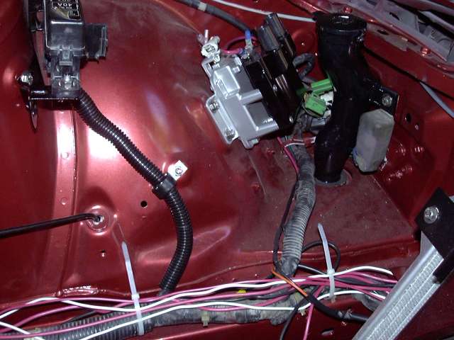
It was now time to start running the harness for the Microtech. The stock engine harness had already been stripped down to contain only the wiper, alternator and water temp wires, so the Microtech harness was passed through the stock rubber boot and into the interior of the car.

Next, the electrical panel was installed.
The Microtech harness was then laid into place roughly. When I wire standalones, I like to roughly lay the harness where it should go and then bring out leads to each sensor and connection. I then loosely tie with wire ties and start making the connections. After the harness is wired, the sensors check out and engine starts, I then neatly loom everything in the appropriate harness wrap.
With the harness in place, the actual wiring can start. Shown here is some of the wiring to the Crane HI-6 ignition box, and the electric fan relay (far right). The Microtech harness is short, so the leads to the ignition and fan needed to be extended. I ran them along the stock body harness after they lead accross the firewall, over the brake booster and underneath the trailing coil. The Microtech's auxillary output is being used to control the e-fan in my case, but it will also run almost anything you can think of (idle motor, boost solenoid, nitrous, microfueller, etc.). Note the modern WeatherPack style connector used to connect the ignition box. These connectors provide a totally weather tight connection and are vasty superior to the connectors that came with the FC. But they are certainly not cheap. The jumbled mess of wire near the relays is the old foglight wiring, which will be trimmed and set up properly later on.

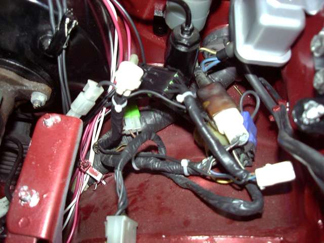
Here you can see the beginnings of my engine bay harness along the stock body harness, as well as the wiring to the leading coil. The orange and black wires are from the Crane box, and as you can see the stock igniter is totally bypassed. It's function has been superceeded by the Microtech and Crane box, so it's only purpose now is as a place to mount the leading coil.
This is a rather poor image of the wiring around the trailing coil. Two more WeatherPack connectors have been used, a single (hidden) and a triple (visible). The triple is the ONLY place the Microtech harness connects to the body harness. It contains the pink 12V ignition wire, and the select and trigger wire for the trailing coil. The single connector is tied to 12V ignition as well, to turn the Crane box on. I decided that I would rather use two connectors instead of a quad connector for organization purposes. It may look messy now, but once I know everything works it will get tidied.
Time to wire the primary injector connectors. First, each wire is stripped about 1/2" from the end. Adhesive lined double-wall heatshrink is slipped over the wire, then the stripped leads are twisted together solidly, then the joint is soldered. I am super anal about my wiring. In a sense, I view wiring as sort of an art and thus try very hard to make it as perfect and reliable as possible. This means NO CRIMPS unless they cannot be avoided, no electrical tape, always new connectors (if possible), and intelligent wire routing and looming. I put large amount of thought into how each wire is to be run and connected to avoid having to cut or splice it later. To be perfectly honest, I have NEVER seen a wiring job done by someone else that I have been happy with.

After they are soldered, heat shrink tubing is used to insulate. I only use double walled adhesive lined shrink tubing for this. It costs about 3x as much as "regular" tubing, but is about 10x stronger. The adhesive lining seals the joint permanently, and adds a lot of strength to the connection. Because of the adhesive, it is almost impossible for water to penetrate and thus you will never see corrosion at the joint like most harnesses (even OEM harnesses) have. Those injector connectors are the modern WeatherPack version of what was used by Mazda. They are sealed both at the injector itself, and at the top where the wires enter.
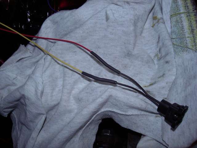
Here are the completed injector connections. You can't easily tell from the picture, but the wires to each injector are exactly as long as each other. The red wire on each injector faces the rear of the car, and the heatshrink has been staggered between injectors as to not cause bump in the harness.
Now back inside the car, some wiring takes place at the electrical panel. Again, it's pretty messy right now, but will get cleaned up when the harness is finalized. The thick red and black wires are the battery cables. They are 4 AWG cables (4 AWG is a little thin actually, I recommend 2 and bigger) that lead back to the passenger storage bin. On each end, the appropriate lug has been installed and soldered in place. I prefer to solder these lugs even though I have the proper (and expensive!) crimper. I just feel that it is a more permanent connection. Again, the connections were covered with adhesive filled heatshrink, then the appropriate colour of heatshrink was used to make them a little more visually appealing. The red heatshrink is just single wall stuff, so all it's good for is aesthetics anyway. The thinner red wire is from the alternator. In the final configuration, it will connect through a circuit breaker. The two black wires are ground for the ECU and fuel pump. On final connection, the paint will be scraped down to bare metal and dielectric grease will be applied.
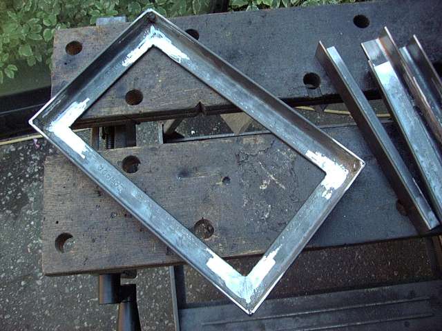
Since the battery is being relocated, a battery box is needed. Most people seem to use those plastic boxes available at auto/marine stores, but I have never been happy with them. They're very flimsey, and would basically do nothing to stop a battery from becoming a 50 LB+ projectile in the event of a collision. Even though the battery is supposed to be strapped or tied to the car, this is rarely done correctly either. NHRA (and I think SCCA?) rules specify that the battery is to be secured to the car, and not the battery box. Thus, I decided to build a sturdy battery box which has mounts that will also serve to secure the tiedown strap to the car. The first step was to measure the battery (an old Optima was used as a guide) and cut the angle iron to size.
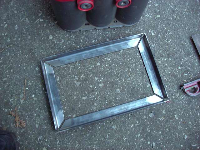
The box was then welded together....
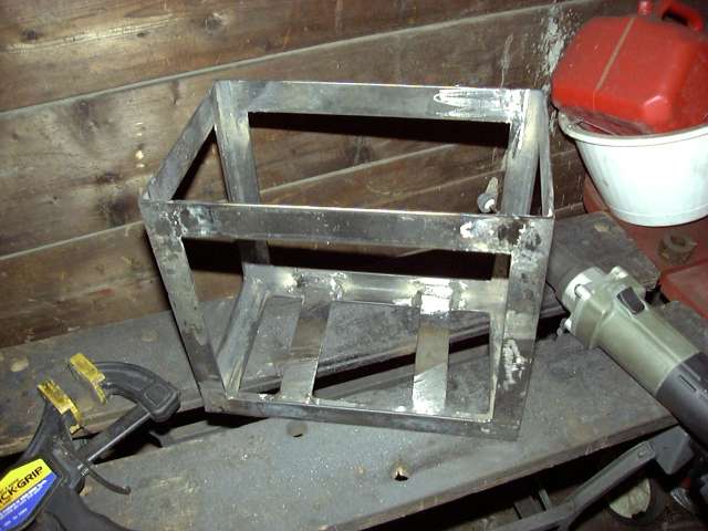
...and corners were installed.
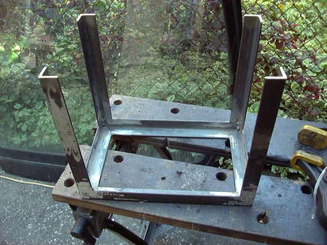
I finished off the box by welding some 1.5" wide strips at the top, and then ground down all the welds.
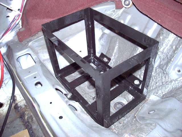
Once mounts were welded on and the box was painted with POR-15 (it's resistance to acid makes it perfect for the job), it was bolted into the car. There are three mounts; one at the front and two in the back. Each attaches with an M8 x 1.5 stainless bolt.
Some trimming of the stock storage bin lid was required as well as removal of the fabric "bag". The lid still closes fully and locks.

Finally, here's the underside of the car. Large stainless washers were used to distribute the load of the box over the thin metal of the underbody. Note that this is just a mock-up for picture purposes as I didn't have bolts long enough to fit the lockwashers. There is rust and gunk on the suspension arm since I didn't bother painting them.
And that's about it for now. Next major task is to build the upper intake, but I'm saving that until I can post a thread which can cover the entire process. After the intake, there's the starter, ground and battery wiring, the secondary injectors, intercooler piping, TID, etc. It's getting closer and closer to being started. However, that will not take place this year. The cold weather is starting to roll in, and we will probably see show in late November. I'm not going to rush myself to get it started only to have to put everything away for the snow. That's OK, since it means that the car will start in late spring, which will give me the entire summer to break it in and then install the big turbo. :)
|
|
|
Kale
Nobel Prize Winner

Canada
795 Posts |
Posted - Oct 16 2005 : 9:10:37 PM
|
Geez man! Let me know when you're done so I can come worship your car! That's an awesome amount of blood sweat and tears your putting in there!
On a more serious note, maybe you should buy some disposible paper overalls from a lab supply store or something the next time you paint. One of those and a mask/face shield covered with disposible clear plastic should keep you from becoming one with the paint again.
|
 |
|
|
Aaron Cake
Administrator
Canada
6718 Posts |
Posted - Oct 17 2005 : 09:45:17 AM
|
If I ever do something like that again, I will disassemble the car and put the body on a rotisserie. Painting overhead is just not going to happen again for so many reasons. .
|
|
|
|
cirvin
Nobel Prize Winner
USA
1542 Posts |
Posted - Oct 17 2005 : 9:09:07 PM

|
My god, all of this to bridgeport the engine!
All the work you do on this car, it's inspireing. Makes me want to get into a project like this.
I will join Kale in the worship of your car, for it is truely awsome in every sense of the word.

http://daxter12.topcities.com <Updated:July |
|
|
|
Aaron Cake
Administrator
Canada
6718 Posts |
Posted - Oct 18 2005 : 09:59:47 AM
|
The most amusing part is that all of this came about because I needed to replace the clutch. I figured that since the transmission was already out, I might as well have it rebuilt. Then while the shop was doing the transmission, I would rebuild the engine...and it just snowballed from there. Ironically, porting and building the engine has so far been one of the smallest parts fo the project!
However, I must say that the words "just" and "bridgeport" should not go together in the same sentence. 
|
|
|
|
cirvin
Nobel Prize Winner
USA
1542 Posts |
Posted - Oct 22 2005 : 8:35:56 PM
|
Which is why I didn't put them together.
So you did all of this in your garage and basement?
http://daxter12.topcities.com <Updated:July |
|
|
|
Aaron Cake
Administrator
Canada
6718 Posts |
Posted - Oct 23 2005 : 3:17:01 PM
|
quote:
So you did all of this in your garage and basement?
And the driveway. I prefer to do engine work inside (the nice thing is that the rotary block is about 200 LBS, so it can easily be carried in and out of the house), messy work in the driveway, and final assembly on the car in the garage.
|
|
|
|
Kevinlekiller
Member

Bangladesh
45 Posts |
Posted - Oct 30 2005 : 01:39:26 AM
|
Sweet project , I worship you.
Bab Himself
Edited by - kevinlekiller on Oct 30 2005 01:42:17 AM |
|
|
| |
Topic |
|
|
|