| Author |
 Topic Topic  |
|
audioguru
Nobel Prize Winner

Canada
4218 Posts |
 Posted - Apr 11 2007 : 3:03:38 PM Posted - Apr 11 2007 : 3:03:38 PM


|
2 hours per day is not long enough to charge a big car battery.
Half of a 556 is a 555. Make a 50Hz oscillator with one half of the 556. Then connect pin 2 to pin 6 together as an input(on a 555, look to see which pins on a 556) then it is an inverter.
A CD4027 is completely different to a CD4047. |
 |
|
|
sid_ric
New Member
Uganda
3 Posts |
|
|
kivdenn
Nobel Prize Winner
Uganda
535 Posts |
Posted - Apr 13 2007 : 09:44:50 AM
|
| Hi guys I would like to try some other FET power inverter circuit because Gary\s circuit kind of delays to turn on for the first 1/4 second.COuld we solve this or opt for other circuits |
|
|
|
audioguru
Nobel Prize Winner
Canada
4218 Posts |
Posted - Apr 13 2007 : 11:49:52 AM
|
Hi Sid,
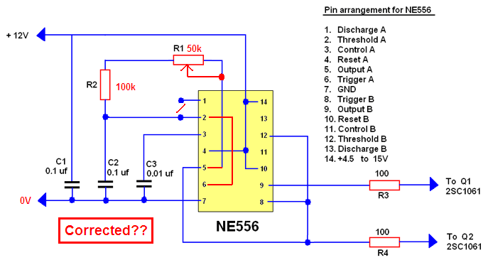
Your 556 doesn't make a square-wave. It makes an assymetrical rectangular wave.
I modified it so its output charges and discharges the capacitor through the timing resistors equally.
I didn't check the frequency but maybe the pot I added will adjust to the correct frequency.
Hi Kivden,
You forgot to provide a link to Gary's inverter. I don't have time to search for it.
Download Attachment:  556 push-pull oscillator.PNG 556 push-pull oscillator.PNG
35.72 KB
 |
|
|
|
Binary 1011001101
Nobel Prize Winner
United Kingdom
569 Posts |
Posted - Apr 13 2007 : 5:58:09 PM
|
Ive been trying to make this inverter on this page posted by audiougru, http://aaroncake.net/forum/topic.asp?TOPIC_ID=2996&whichpage=24 uses the CD4047 a/bisable mutivibrator IC, I also cannot find this so I used a 555 fed into a fip-flop driving transistors, The output is a low voltage of 18VAC, the input is 12.8V at 2 amps, transformer used was a 240v to 12-0-12. If I use the 0-12 windings it outputs a voltage so high it makes my multimeter spark and frazle inside!
Anyone know why? Also I have not used the op-amps and the small transistors to drive the 2N3055.
Thanks. |
|
|
|
audioguru
Nobel Prize Winner
Canada
4218 Posts |
Posted - Apr 13 2007 : 9:37:07 PM
|
Binary,
Yor oscillator/flip-flops have an input of 12.8VDC and the output is 18VAC? How?
If you feed 18VAC into the 12V winding of a 240V transformer then its output will be 18/12 x 240= 360VAC.
Please upload your schematic. |
|
|
|
Binary 1011001101
Nobel Prize Winner
United Kingdom
569 Posts |
Posted - Apr 14 2007 : 03:12:13 AM
|
I don't know why, its really weird.
Here is the schematitc http://i96.photobucket.com/albums/l178/binary10101/inverter.jpg
Ok screw what I said in my previous post, It gives out the HV when using the schematic above, I can even draw small sparks... |
Edited by - Binary 1011001101 on Apr 14 2007 09:24:38 AM |
|
|
|
audioguru
Nobel Prize Winner
Canada
4218 Posts |
Posted - Apr 14 2007 : 10:25:04 AM
|
Binary,
You saved your schematic as a fuzzy JPG file type instead of a very clear GIF or PNG file type. Why???
Then you uploaded it to PhotoBucket instead of here. Why???
I calculate the frequency of your 555 oscillator at 68Hz then the flip-flop divides it down to only 34Hz which is way too low. A capacitor marked "104" is 0.1uF.
The minimum input voltage for a 7812 regulator is 14.5V but you have only 12.8V. So it won't regulate and its output voltage is about only 10V.
You don't show which flip-flop IC you are using. It must be Cmos because TTL would fry with a 12V supply. The output current of Cmos with a 12V supply is only about 15mA which is way too low to drive 2N3055 transistors for power.
Your transformer is way too small for an inverter. Its max power is only 12V x 200mA= 2.4W. The output voltage would be very freaky without a load. |
|
|
|
Binary 1011001101
Nobel Prize Winner
United Kingdom
569 Posts |
Posted - Apr 14 2007 : 11:17:20 AM
|
I saved it as a JPG because express sch saves it as that and no other options, most of the time it is ok.
You can upload to here? I didn't know that, how do I do it
The flip flop I used was a SN74LS76AN. I also tried a darlington pair to drive the 3055, the low power BFY51 transistor hot VERY hot
Anyway, If I use your circuit without the op-amps and in place of the CD4047 there is a 555 and flip-flop giving the correct frequany would it work?
|
|
|
|
fedfray
New Member
Indonesia
1 Posts |
Posted - Apr 23 2007 : 12:53:30 PM
|
| hi audioguru.... u r an expert for electronic for me...can i ask something? for 500w inverter...can i paralel 6 trafo 10 A at 12 Vac for replacing 60 Ampere trafo 12/220 vac. i think it's more cheaper |
|
|
|
audioguru
Nobel Prize Winner
Canada
4218 Posts |
Posted - Apr 23 2007 : 4:01:16 PM
|
Hi Binary,
The flip-flop is TTL which needs a regulated 5V supply.Its output doesn't go to a high enough voltage for this circuit.
Hi Fedfray,
I don't think you sould connect transformers in parallel. They might not be exactly the same which would cause a high current to flow between them. |
|
|
|
Binary 1011001101
Nobel Prize Winner
United Kingdom
569 Posts |
Posted - Apr 23 2007 : 4:42:41 PM
|
| Ok so would it work if I pass it through a high gain transistor to power to 3055s? |
|
|
|
audioguru
Nobel Prize Winner
Canada
4218 Posts |
Posted - Apr 23 2007 : 7:36:05 PM
|
Hi Binary,
Two 2N3055 transistors in an inverter would allow an output power of only about 80W.
The 2N3055 has a max 3V saturation voltage loss spec at 10A when its base current is 3.3A. The max base-emitter voltage is 1.5V at 4A and might be 2.5V at 8A. A TIP41 transistor to drive each 2N3055 has a max base-emitter voltage of about 1.5V at 3.3A and its base current would need to be at least 220mA. A 3rd driver transistor is needed to supply the 220mA and its base-emitter voltage is about 1V so the total voltage needed to drive the transistors is 2.5V + 1.5V + 1V= 5V. The max output voltage from a TTL flip-flop is only about 3.5V. |
|
|
|
Binary 1011001101
Nobel Prize Winner
United Kingdom
569 Posts |
Posted - Apr 24 2007 : 02:28:42 AM
|
Stupidly ive allready started making it wihtout knowing it will work.
So what if I put a opto-couple on it, not to isolate but to amplify the signal, a LED only needs about 3.5V and the other half I could make into a darlingtion pair...
Just more ideas, |
|
|
|
audioguru
Nobel Prize Winner
Canada
4218 Posts |
Posted - Apr 24 2007 : 08:04:22 AM
|
quote:
Originally posted by Binary 1011001101
So what if I put a opto-couple on it, not to isolate but to amplify the signal
No. Look at its datasheet. Many optical isolators don't amplify. 10mA in produces only 2mA out.
quote:
a LED only needs about 3.5V
No. Look at its datasheet. A white or blue LED is about 3.5V. The IR LED in an optical isolator is about only 1.2V.
In the 500W inverter that I fixed there are four 2N3055 transistors in parallel at the output on each side. They are driven by another 2N3055, which is driven by a medium power transistor, which is driven by an opamp, which is driven from a cmos oscillator operating with a 12V supply. |
|
|
|
Topic |
|