| Author |
 Topic Topic  |
|
audioguru
Nobel Prize Winner

Canada
4218 Posts |
 Posted - Dec 19 2006 : 5:04:23 PM Posted - Dec 19 2006 : 5:04:23 PM


|
Hi Tim,
Do those inverters use high frequency PWM to make a sine-wave output?
Then the Mosfets operate like a class-D power amplifier. |
 |
|
|
tim
Mad Scientist

198 Posts |
Posted - Dec 19 2006 : 6:13:15 PM
|
| well this inverter im working on is of course , like most made in japan or china and from what i can see is its got a row of 55volt 80 amp mosfets VIA PWM DRIVING THESE SMALL TRANSFORMERS UP TO 147 VOLTS ON THE SECONDARY THEN ITS SPLIT IN 2 STAGES AGAIN VIA PWM AND HAS A ROW OF 200 VOLT 18 AMP MOSFETS TO SPLIT THE DC LEAVING AC. BUT I DONT KNOW THE HZ ON THE PRIMARY OR SECONDARY , THERE ARE 2 DRIVES, HOWEVER IT LOOKS LIKE THE BOTH SIDES SHARE THE SAME RESISTOR THAT SETS THE HZ. |
|
|
|
AMEERQURESHI
New Member
1 Posts |
Posted - Dec 27 2006 : 12:36:13 AM
|
I am looking for a circuit diagram to make 500W 24 volt battery inverter,
If some one have, pl mail me, thank you very much,
Ameer |
|
|
|
jeswinjames24
New Member
India
1 Posts |
Posted - Jan 04 2007 : 12:47:01 PM

|
Could you please sent me the mocified circuit schematic of the 12v DC to 120 v AC inverter.
I m a student and need to submit it as a project, please reply me in 18 hrs. |
|
|
|
audioguru
Nobel Prize Winner
Canada
4218 Posts |
Posted - Jan 04 2007 : 1:31:06 PM
|
| There is no modified schematic. It needs an entirely different design for it to work properly. |
|
|
|
audioguru
Nobel Prize Winner
Canada
4218 Posts |
Posted - Jan 05 2007 : 10:39:39 AM
|
Attachments can be made here???
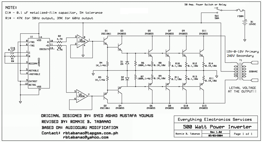
Here is a 500W square-wave inverter that works.
Here it is for low power.
Download Attachment:  500Watts_Inverter-small.PNG 500Watts_Inverter-small.PNG
161.26 KB
Download Attachment: 100W inverter.GIF
15.87 KB
 |
|
|
|
bala
New Member
India
2 Posts |
Posted - Jan 10 2007 : 06:32:40 AM

|
| i tried this circuit.still i dont get output. what are all the things i have to check? |
boobalan |
|
|
|
audioguru
Nobel Prize Winner
Canada
4218 Posts |
Posted - Jan 10 2007 : 09:52:46 AM
|
Boob,
Which circuit did you make?
Check that the oscillator is oscillating. |
|
|
|
CurrentOverflow
Mad Scientist
Canada
311 Posts |
Posted - Jan 10 2007 : 7:34:44 PM

|
| I was just wondering how .1 ohm resistors take a load of transistors thx :) |
~Mike~
Theres 10 kinds of people, those who understand binary and those who don't |
|
|
|
audioguru
Nobel Prize Winner
Canada
4218 Posts |
Posted - Jan 10 2007 : 9:49:23 PM
|
Are you talking about the 0.1 ohm emitter resistors on the 500W inverter? They help make the paralleled transistors share the current.
Transistors with the same part number are different. At a collector current of 12.5A three could have a base-emitter voltage of 2.0V while one has a base-emitter voltage of 1.5v and it would be turned on hard but the others would not be turned on much. A 0.1 ohm resistor adds 1.25V to the base-emitter voltage of the one that conducts the most so the others can turn on and share the current. |
|
|
|
bala
New Member
India
2 Posts |
Posted - Jan 11 2007 : 12:14:03 AM
|
| i tried that transistor based astable multivibrator circuit in the inverter. there is only two transistor ,but one transistor get heated always, the another transistor doesn't work. so i just confused. how can i check the oscillation? |
boobalan |
|
|
|
audioguru
Nobel Prize Winner
Canada
4218 Posts |
Posted - Jan 11 2007 : 10:10:44 AM
|
Hi Boob,
Both transistors must work in a transistor multivibrator oscillator. Replace the transistor that does not work.
Then the capacitors will blow up. |
|
|
|
tim
Mad Scientist
198 Posts |
Posted - Jan 13 2007 : 9:26:08 PM
|
| ok guys ive got a better idea pick up a cheap chinese inverter then desolder every conponent then put it back together. this might be less stressful, lol, ...... |
|
|
|
Nnamdi
New Member
Nigeria
1 Posts |
Posted - Jan 15 2007 : 08:54:40 AM
|
quote:
Originally posted by pprabhu
Can anybody tell me how to obtain a 500W,12vdc to 220vac circuit diagram with output current of about 3Amperes.
|
|
|
|
gcarson
New Member
USA
1 Posts |
Posted - Jan 17 2007 : 10:05:04 PM
|
| I have a 400amp pipeline welder that has no inverter for 120/240. Is it possible to purchase such a addition and is it practical. I am looking for a source of power when the power grid goes down. |
|
|
|
Topic |
|