| T O P I C R E V I E W |
| JUAN DELA CRUZ |
Posted - May 17 2008 : 08:35:47 AM
Hi everyone 
>>> I just wanna share this
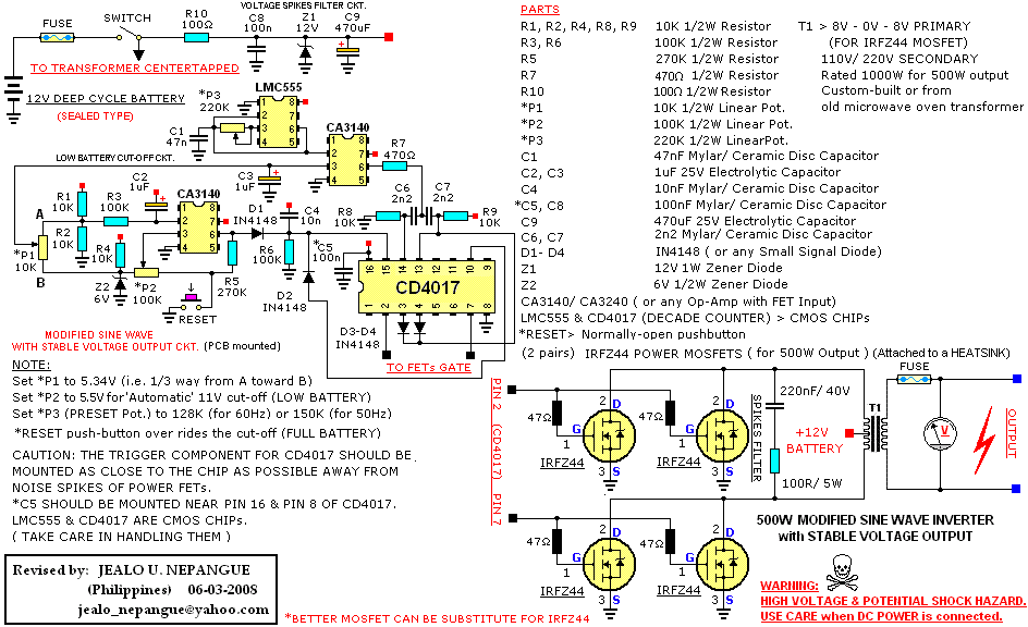
Simple Low Frequency Type Power Inverter Circuit
(Modified-Sinewave Output)
>>> It is a simple circuit yet effective. Hobbyist can built it as a emergency power source and use it whenever it is needed.
>>> Construct at your own risks. Be careful when D.C. Power is connected ! ! !
Download Attachment:  Modified-Sinewave Inverter.png Modified-Sinewave Inverter.png
35.71 KB
edit: Updated Diagram Posted |
| 15 L A T E S T R E P L I E S (Newest First) |
| pebe |
Posted - Aug 28 2010 : 12:53:34 PM
Juan, Have you deleted your last post - I cannot see it. |
| sergiosparks |
Posted - Jan 11 2010 : 08:10:11 AM
Juan de la Cruz if you are woking on something thats power hungry
get a new battery it will save you a lot of time. |
| wasssup1990 |
Posted - Sep 17 2009 : 09:44:11 AM
WTF? What a coincidence? Look at the date of audioguru's last post and kivdenn's. |
| kivdenn |
Posted - Sep 17 2009 : 06:07:18 AM
Hi Juan please help me with yo LVD circuit that uses a relay switch. Thanks |
| audioguru |
Posted - Sep 17 2008 : 4:56:33 PM
The labels for the parts are a very light pastel shade and can hardly be seen. I use BLACK that can be seen. |
| mrgone |
Posted - Jun 10 2008 : 09:13:21 AM
It's pretty good! Here is a small example:
Download Attachment: Dual-SW.GIF
5.81 KB
 |
| JUAN DELA CRUZ |
Posted - May 28 2008 : 05:42:01 AM
quote:
Originally posted by JUAN DELA CRUZ
quote:
Originally posted by wasssup1990
This one's pretty good, and it's free. I think mrgone is familure with its interface, so if you can get a hold of him he might help you.
http://www.cadsoft.de/
Thanks FOR YOUR REPLY
I'LL TRY THIS ONE http://www.cadsoft.de/
|
| pebe |
Posted - May 28 2008 : 04:02:42 AM
quote:
Hi Audioguru
I'am sorry about that fuzzy JPG File for the reason that I can't attached PNG file & GIF file has more color losses (I didn't use any special software) in making this schematic diagram just the ordinary 'Paint' in my PC.
Do you know any software that can be download from the internet for free so that I can make schematic diagram more effectively????Thanks..
I use the ordinary 'Paint' prog. Although when saving as a .GIF file it warns you about loss of colours, there is no loss of basic colours. I think you only lose pastel shades. |
| wasssup1990 |
Posted - May 28 2008 : 02:58:25 AM
This one's pretty good, and it's free. I think mrgone is familure with its interface, so if you can get a hold of him he might help you.
http://www.cadsoft.de/ |
| JUAN DELA CRUZ |
Posted - May 28 2008 : 12:20:17 AM
quote:
Originally posted by audioguru
Hi Juan,
Your schematic was saved as a fuzzy JPG file type which has losses. if you saved it as a GIF or PNG file type then it would be much clearer.
Hi Audioguru
I'am sorry about that fuzzy JPG File for the reason that I can't attached PNG file & GIF file has more color losses (I didn't use any special software) in making this schematic diagram just the ordinary 'Paint' in my PC.
Do you know any software that can be download from the internet for free so that I can make schematic diagram more effectively????Thanks.. |
| audioguru |
Posted - May 28 2008 : 12:02:38 AM
Hi Juan,
Your schematic was saved as a fuzzy JPG file type which has losses. if you saved it as a GIF or PNG file type then it would be much clearer. |
| pebe |
Posted - May 24 2008 : 08:54:30 AM
Hi Juan,
You already have a 100ohm series resistor R11 for decoupling, so you can leave out R3.
For more reliable operation, increase C4 to 1µF.
Using the revised circuit, P2 should be set to 5V, not 5.34V
|
| pebe |
Posted - May 23 2008 : 12:38:17 AM
Hi Juan,
This circuit delays the cut-out better when the inverter is switched on.
Download Attachment: Modified Sine Wave 4.GIF
4.55 KB
 |
| JUAN DELA CRUZ |
Posted - May 22 2008 : 9:22:58 PM
quote:
Originally posted by wasssup1990
Very cool. Have you thought of an inverter that, for example:
Boosts the battery voltage up to +240VDC/+120VDC & -240VDC/-120VDC and then modulates a 50/60Hz sinewave onto the PWM carrier with power being sourced from those two voltage rails? That would be very efficient wouldn't it?
Are you making this project for fun?
WASSSUP.......Johnny
The inverter that you are talking about is much "EXPENSIVE & complicated high frequency Pulse-Width-Modulation circuit to make a pure sine-wave W/ voltage feedback to regulate the level of their output voltage. I wouldn't build that kind of inverter.I would buy instead (but I don't have enough budget to buy expensive inverter, hence I build an inverter from Scratch( old components from junkshop yet it is still functioning very well)
My modified sine inverter is "CHEAPER TO BUILD" (w/ huge Xformer from microwave oven) w/ "STABLE VOLTAGE OUTPUT".
I'am just using it when their is a power cut-off.
CHEAPER BUT EFFECTIVE |
| pebe |
Posted - May 22 2008 : 11:37:43 AM
Here is the undervoltage cut-out. It uses another op-amp.
Under normal conditions, the output of the op-amp is low, so P2 and R10 form a potential divider between the 6V zener at ‘B’ and 0V. P2 slider is set to give just over 5.3V.
Modified half battery voltage comes in from P1 slider. Normally this is higher than 5.3V. The –ve input is higher than the +ve input so the op-amp’s output is low. D2 is reverse biased.
When the battery volts drop to 10V, point ‘A’ will be at 5.3V. The +ve input will then be higher than the -ve input so the op-amp output will go high. R10 now pulls up the +ve input to give positive feedback to assist the action.
D2 now conducts pulling up the reset pin of the 4017 and stops it counting. Its count is now at ‘0’ and the FETS have no drive.
C7 keeps the +ve input low at start-up and keeps the circuit off. The reset button over rides the cut-out.
Edit Note: Circuit has been edited.
Download Attachment: Modified Sine Wave 3.GIF
4.29 KB
 |