| Author |
 Topic Topic  |
|
JUAN DELA CRUZ
Mad Scientist

Philippines
476 Posts |
 Posted - May 17 2008 : 08:35:47 AM Posted - May 17 2008 : 08:35:47 AM


|
Hi everyone 
>>> I just wanna share this
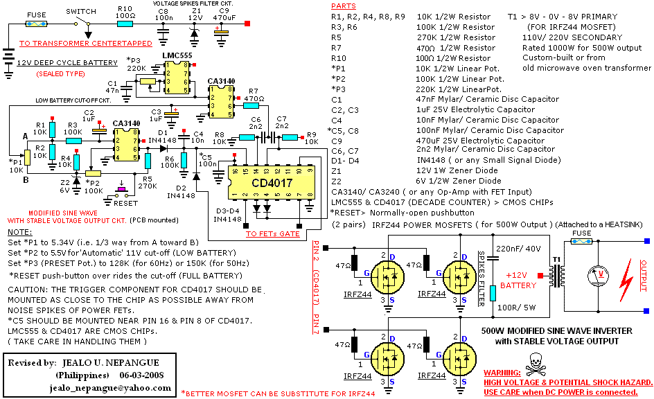
Simple Low Frequency Type Power Inverter Circuit
(Modified-Sinewave Output)
>>> It is a simple circuit yet effective. Hobbyist can built it as a emergency power source and use it whenever it is needed.
>>> Construct at your own risks. Be careful when D.C. Power is connected ! ! !
Download Attachment:  Modified-Sinewave Inverter.png Modified-Sinewave Inverter.png
35.71 KB
edit: Updated Diagram Posted |
juan dela cruz
Penniless INVENTOR |
Edited by - JUAN DELA CRUZ on Sep 02 2010 12:58:58 PM |
|
|
pebe
Nobel Prize Winner

United Kingdom
1078 Posts |
Posted - May 17 2008 : 10:15:53 AM
|
You can fit circuitry to protect the SUPPLY from a short circuit load, but you cannot protect the LOAD.
The maximum voltage at the output of the supply will be set by the state of charge of the battery and the turns ratio of the transformer. So what 'high voltage' protection do you mean? |
 |
|
|
pebe
Nobel Prize Winner
United Kingdom
1078 Posts |
Posted - May 18 2008 : 02:29:29 AM
|
So you mean stabilizing the input voltage? I don't think there is a simple way to do that. But if you are running the battery down to 8V then that's far too low.
A zener would not be suitable because it is shunting off surplus power - very wasteful. What is needed is some form of series limiter.
One way of stabilizing the output voltage might be to measure the peak amplitude of the output voltage and use that to control the pulse width going into the transformer - but that method may have problems and, again, it's not simple. |
|
|
|
pebe
Nobel Prize Winner
United Kingdom
1078 Posts |
Posted - May 18 2008 : 09:31:05 AM
|
quote:
I used 2 pair IRFZ44 mosfet in my modified sine inverter w/c have a total voltage loss of 0.84V.
(12V- 0.84V = 11.16V x 0.707RMS = 7.89VRMS)....that's why I used 8V- 0V - 8V primary Xformer..
I was making the point that you should not discharge your battery down to 8V. The absolute minimum should be 10V
quote:
.....So you mean a "bleeder resistor" in series w/ Zener diode????
What will be the amount of Zener voltage & Bleeder Resistor?????
You asked:
�.........do you think a Zener diode at the output of the Power mosfet is the answer to regulate the voltage before coming to the primary side of the Xformer,hence the secondary voltage of the Xforer will be fixed???�
And I said a zener would not be suitable. It would need some sort of series current limiting device that would drop the voltage applied to the transformer.
quote:
...So you mean a feedback?????
.........or a Automatic Voltage Control?????
I meant using feedback to obtain automatic voltage control.
|
|
|
|
audioguru
Nobel Prize Winner
Canada
4218 Posts |
Posted - May 18 2008 : 10:43:27 AM
|
Most inverters that have a complicated high frequency Pulse-Width-Modulation circuit to make a pure sine-wave have voltage feedback to regulate the level of their output voltage.
This modified sine-wave inverter circuit is too simple for voltage regulation.
A zener diode converts extra voltage into heat. You don't want to short your inverter with a 700W zener diode. |
|
|
|
mrgone
Nobel Prize Winner
USA
1176 Posts |
Posted - May 18 2008 : 11:41:24 AM
|
| You need a "Crow Bar" circuit. It uses SCRs to short circuit the output of the power supply. |
|
|
|
audioguru
Nobel Prize Winner
Canada
4218 Posts |
Posted - May 18 2008 : 12:42:25 PM
|
quote:
Originally posted by mrgone
You need a "Crow Bar" circuit. It uses SCRs to short circuit the output of the power supply.
Blowing the fuse with a crowbar circuit is not a very good way to regulate the output voltage of the inverter circuit.
When the battery is freshly charged then its voltage is 13.8V. Then the output voltage of the inverter is too high.
When the battery is almost desd then its voltage is 10V. Then the output voltage of the inverter is too low.
That is how a simple inverter circuit works. It doesn't have voltage regulation.
The transformer also drops the output voltage when it is loaded. |
|
|
|
audioguru
Nobel Prize Winner
Canada
4218 Posts |
Posted - May 19 2008 : 12:22:04 AM
|
The Mosfets in the simple inverter switch on completely and switch off completely so that they don't overheat. If you have a circuit that turns them on only partially then they will overheat.
A crowbar circuit is used in a DC circuit and if the voltage becomes too high because a part has failed then the SCR conducts to blow the fuse. You don't have DC and you don't want to blow the fuse. |
|
|
|
pebe
Nobel Prize Winner
United Kingdom
1078 Posts |
Posted - May 19 2008 : 04:20:57 AM
|
quote:
Originally posted by JUAN DELA CRUZ
[br
Thank you Mr. Pebe.......
What will be that "series current limiting device that would drop the voltage applied to the primary winding of the Xformer???
.......a power resistor????
I said, "So you mean stabilizing the input voltage? I don't think there is a simple way to do that."
And there isn't!
In your circuit it would mean modifying the pulse width going into the transformer - probably with feedback from the output taken into account. It would mean a complete redesign of the oscillator stages. In fact, a different circuit. |
|
|
|
pebe
Nobel Prize Winner
United Kingdom
1078 Posts |
Posted - May 19 2008 : 05:02:59 AM
|
Why did I just know you were going to ask that question?
No I haven't got a circuit, and if I were to design one I wouldn't have the time or components to build and test it at the moment. |
|
|
|
pebe
Nobel Prize Winner
United Kingdom
1078 Posts |
Posted - May 19 2008 : 1:01:11 PM
|
| I've thought of an idea. I'll come up with something in a few days. |
|
|
|
pebe
Nobel Prize Winner
United Kingdom
1078 Posts |
Posted - May 20 2008 : 05:47:30 AM
|
I thought you may be interested in the way I propose to get the variable duty cycle for the modified sine wave inverter. The circuit will use an LMC555 timer to generate a triangular wave. Its peak-to-peak voltage is from 1/3 Supply to 2/3 Supply. The waveform is fed into a slicer to generate the pulses.
With a 12V nominal battery the slice level is 6V to give a 50:50 waveform. When the battery voltage drops to 10V the �pulse on� period needs to be increased by 1.2 times (12/10) to compensate. So the circuitry will automatically adjust the slice level to 5.34V ([5V-3.3V] x 1.2 + 3.3).
More in a few days.
Download Attachment: Modified Sine Wave 1.GIF
9.33 KB
 |
|
|
|
audioguru
Nobel Prize Winner
Canada
4218 Posts |
Posted - May 20 2008 : 11:18:21 AM
|
Why not just use a PWM chip like a TL494? Then you will have a square-wave inverter with voltage regulation.
Maybe many more parts can be added to make it into a modified sine-wave output. |
|
|
|
pebe
Nobel Prize Winner
United Kingdom
1078 Posts |
Posted - May 20 2008 : 12:30:04 PM
|
Because I've not used that chip. If I am going to give someone an untested circuit that I a fair degree of faith in, then it will be using components which I have had 'hands on' experience with.
|
|
|
|
pebe
Nobel Prize Winner
United Kingdom
1078 Posts |
Posted - May 21 2008 : 01:53:55 AM
|
I don't know what you mean by DC component - unless you mean the mean DC of each half cycle,
You need to be able to adjust the pulse width fed to the FETs, ie, ratio of 'on' and 'off' times. |
|
|
|
pebe
Nobel Prize Winner
United Kingdom
1078 Posts |
Posted - May 21 2008 : 06:22:04 AM
|
quote:
Originally posted by JUAN DELA CRUZ
Do you think this will be answer to stabilize the output voltage of my modified sine inverter???
Hi Juan,
No, that circuit alters the frequency.
Here is the circuit I promised. I hope it works for you, but as I said, it�s untested!
I�ll go through it stage by stage.
The LMC555 generates a triangular waveform. It is not a perfect shape but in this application where only a small portion of the charge/discharge curve is used, it does not matter. A constant current fed sawtooth generator could have been used but that would have meant more components. The p-p amplitude is from 1/3 to 2/3 of the supply voltage so its DC level will drop with a drop in battery voltage. Its frequency is determined by C1/R1. It runs at twice the required frequency so a half cycle period is equal to 5ms for a 50Hz system and 4.17ms for 60Hz. The time for a period can be calculated from Time = 0.693 x C1 x R1. Make sure you use this CMOS chip - not the bipolar one.
The waveform is fed to an op amp. Just about any one can be used provided its input stages are FETs. The waveform is fed to its inverting input. The slicing voltage is fed to its non-inverting stage. When the battery supply is 12V the voltages at A and B are both 6V and the output waveform will be pulses with a 50:50 ratio.
As I mentioned in the previous post, when the battery voltage has fallen to 10V the slicing level needs to be 5.34V. Point �A� will be at 5V and point �B� will be at 6V so the slider of P1 needs to be set for 5.34V, ie. about 1/3 way from A towards B. In fact, P1 could be replaced with a 10K resistor and the feed to the amp taken from point �A�. With a 10V battery, compensation would then be 5.333V � which would be near enough.
With a freshly charged battery at 13.8V, point �A� will now rise to narrow the pulse.
Pulses from the amp go through R6 to clock the 4017. This is a decade counter with an output high going in sequence from each of its outputs from 0 to 9 and then repeating. In this case when the count gets to 4, D1 pulls up the reset pin and the count resets back to 0. So the count goes 0, 1, 2, 3, 0, etc..
The count is stepped forward twice for each pulse. The rising leading edge triggers the CK pin. And the falling trailing edge triggers CE . So the sequence is this.
Pulse 1 on = output to 1
Pulse 1 off = output to 2
Pulse 2 on = output to 3
Pulse 2 off = output to 0
And so on.
Note that the correct pulses appear on 1 and 3. If the counter gets out of sync they would appear on the odd numbered pins. To prevent that, D2 and D3 are fitted. Either one will pull up the CE pin and prevent it from clocking. So the next clock pulse will be that from CK, and the counter will get back in sequence.
C6 makes the chip reset to give output high on 0 at startup. C3 smoothes noise at P1 and ensures that pulses are at minimum width (lowest voltage output) at startup.
The 4017 is triggered by pulses so R2 and C2 are a filter to keep out noise from its Vdd supply. Also a 100nF cap should be fitted as close as possible between its Vss and Vdd pins (to avoid �clutter� I have left this off the circuit).
A word of caution. The LMC555 and 4017 chips are CMOS so take care in handling them. The trigger components for the 4017 should be mounted as close to the chip as possible away from noise spikes from the FTEs.
I hope that�s a good enough description. Have fun.
Edit: Diodes are small signal types, eg. 1N4148 etc.
Modified to reposition labels 'CE' and 'CK'.
Download Attachment: Modified Sine Wave 2Mod.GIF
10.19 KB
 |
Edited by - pebe on Dec 31 2009 07:45:08 AM |
|
|
|
Topic |
|