| Rich |
Colour (Sound) Organ |
Tuesday, May 10, 2016 3:49:08 PM |
| I would HIGHLY recommend putting a fuse between Switch and D1. |
| anonymous |
Colour (Sound) Organ |
Sunday, January 18, 2015 6:11:15 PM |
| It is a good sample design. Be careful you could be in dangers getting electric shock by using this design do to component failed. I would not follow this design as is. |
| anonymous |
Colour (Sound) Organ |
Wednesday, November 23, 2011 4:25:48 PM |
| Where can I find a 10K to 600 Ohm transformer? I cannot find anything that is too ridiculously expensive. |
| MIke |
Colour (Sound) Organ |
Monday, October 31, 2011 9:35:17 PM |
| I just built this circuit, and it doesn't work, any troubleshooting tips? which way does the transformer go? I've checked the circuit to the schematic and it seems right to me, except I'm not sure about the transformer. |
| Chris |
Colour (Sound) Organ |
Saturday, October 22, 2011 1:11:59 AM |
| Just built this circuit and it works great. Using a RCA connector instead of the mic and connecting it to the audio of my home theater system. |
| Andrew |
Colour (Sound) Organ |
Monday, May 17, 2010 9:48:00 PM |
| C2 should be 50V not 250V, also this circuit works just as well if the mic leads are replaced with left and right in-line stereo |
| Andrew |
Colour (Sound) Organ |
Friday, May 07, 2010 2:55:16 PM |
| I have built this and it works great. For those asking, connecting the two leads from a headphone jack cord or whatever to where the mic leads would be works just as well. |
| metompkin |
Colour (Sound) Organ |
Friday, February 26, 2010 11:48:34 PM |
| How could you get an input from an audio device, instead of a microphone? Thank You! |
| totto |
Colour (Sound) Organ |
Friday, January 22, 2010 4:07:55 AM |
| Any substitutes for the 10k---600 Ohm audio transformer??? Cant seem to locate |
| Mike Schneider |
Colour (Sound) Organ |
Monday, November 16, 2009 7:59:09 AM |
| I've just built this schematic here in my classroom and am having difficulties with it. I noticed when I ordered the crystal microphone from Mouser Electronics that it is polarized but it is not specified in the schematic. I've tried both ways: one way I get a buzz sound and it was stop as I touched the mic, the other I got nothing lol. I'm not quite sure what I'm doing wrong here. I also did a ohm reading on the transformer I ordered as well. I ordered the same one on your parts list however I'm getting a reading of only a few ohms I'm guessing that could be the issue lol. Any ideas would be great. |
| souvik kundu |
Colour (Sound) Organ |
Tuesday, September 15, 2009 1:54:45 PM |
| can i use plugin with vcd or dvd .how? pls reply |
| Jonas Karl Christopher N Agutaya |
Colour (Sound) Organ |
Monday, March 23, 2009 4:02:39 AM |
| Can a 10K:10 ohm-audio transformer be used? If not, what can I do to increase 10 ohms to 600 ohms without changing any other values? |
| anonymous |
Colour (Sound) Organ |
Sunday, January 11, 2009 4:46:38 AM |
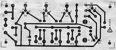
| what is exactly this J1 J2 J3?
how is the connection of resistors R10,R7&R11,R8&R12,R9 |
| Dan |
Colour (Sound) Organ |
Wednesday, October 08, 2008 7:56:05 PM |
| Is there any way to make them more responsive. I made a 120v one and compared to my friends, who made the same thing, It takes a larger audio input signal. For an input, I used compression terminals that connect to the audio transformer (Mouser 42TM114-RC) |
| Jay |
Colour (Sound) Organ |
Tuesday, September 16, 2008 1:30:20 AM |
| can I connect a sound source(CD player) instead of microhone. Plz reply.
Rgds
Jay |
| Burnett |
Colour (Sound) Organ |
Saturday, May 10, 2008 5:17:58 PM |
| Is there a way where instead of there being a mic for your sound input that you could wire either rca cords or like 3-4 3.5 jack inputs for your sound and if so what are the schematics of it....thanks for your time and please email me back |
| anonymous |
Colour (Sound) Organ |
Tuesday, March 11, 2008 3:08:56 AM |
| Could you upload the 12v version for everyone to see? |
| Kermit |
Colour (Sound) Organ |
Saturday, February 23, 2008 5:40:56 PM |
| correction: DC version with SCR (thyristor) wont clear lights after triggered once. Use a transitor instead, no clue what type is best |
| Kermit |
Colour (Sound) Organ |
Saturday, February 23, 2008 11:19:12 AM |
| Changes for 230 V AC Version:
C1 & C2 = 22�f 500V Electrolytic Capacitor
R1 = 100k 1/2 W Resistor
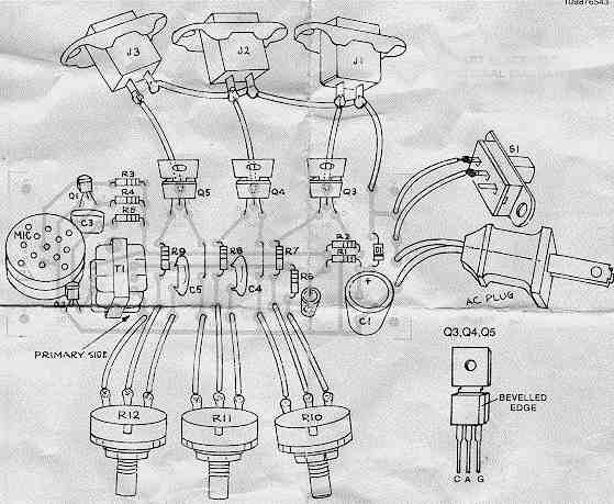
Q3, Q4 & Q5 = C106D or S4003L
Changes for 12 V DC Version:
remove C1, C2 & R2
replace D1 & R1 with a wire
connect +12V on top (common at bottom)
use 12V bulbs ;)
|
| arunprakash |
Colour (Sound) Organ |
Thursday, January 17, 2008 3:27:23 AM |
| What is the cost of colour (sound) organ? |
| anonymous |
Colour (Sound) Organ |
Sunday, December 16, 2007 2:36:04 PM |
| Where can you buy all of the parts because i am doing science fair and i am running out of time.... and what would be the estimated cost please get back to my asap Thank you very much. |
| Pirate Paul |
Colour (Sound) Organ |
Saturday, December 15, 2007 5:39:18 PM |
| The circuit schematic, pictorial, board layout etc shown here are identical to kit #152 offered by Graymark Int'l Inc, POB 2015, Tustin Ca 92781. Beware identification of the primary and secondary of T1 is vague and ambiguous. Obviously, it will not work with T1 installed backwards. For other kits, check Hobbytron.com (where I got the Graymark kit on closeout). |
| nazeel |
Colour (Sound) Organ |
Saturday, December 08, 2007 12:35:01 PM |
| whta is the cost of implementing the circ????????
whhat cld be the cheapest??????
|
| Kyle |
Colour (Sound) Organ |
Thursday, December 06, 2007 11:22:32 AM |
| Is there another type of transformer I could use with the 120v circuit? It's a bit hard to find that transformer and when I did it was an $80 piece. Can a power transformer do the same thing or maybe a less expensive transformer. HELP QUICK PLEASE
Thank You,
Kyle |
| bob |
Colour (Sound) Organ |
Wednesday, November 21, 2007 3:21:20 PM |
| yeah pls send over a 12v version... really might use that.. |
| bradstop |
Colour (Sound) Organ |
Saturday, November 17, 2007 11:47:12 PM |
| Would like to see a 12 volt version |
| anonymous |
Colour (Sound) Organ |
Tuesday, September 18, 2007 2:59:58 PM |
| To help out, an audio transformer is just that an audio transformer. Try finding one on mouser.com or hell radio shack should have them. I dont think I would be building this with out a fuse or at least using a GFI to plug it into ***note GFI may not stay set with the fast changeing current draw this will have.*** None the less use saftey |
| adrian |
Colour (Sound) Organ |
Tuesday, August 28, 2007 3:38:33 AM |
| can you give me the schematics and pcb design for 220 volts
thanks a lot... |
| anonymous |
Colour (Sound) Organ |
Friday, August 10, 2007 6:33:59 AM |
| I am 3rd year computer science student, we are asked to make a project about relays for triggering higher voltages using any devices with PC connection. do you have some idea about this? I can think of anything.
I hope you can help me.
Thanks |
| anonymous |
Colour (Sound) Organ |
Thursday, July 26, 2007 8:25:36 PM |
| hi there.. i am really interested in the project but am lacking few things here.. like what is a audio transformer.. is it a normal transformer ??.. beside what is the AC sockets for isnt it that there should be there lights fixed there ??.. if you can answer me that will be higly appreciated...
ameerhijjawi@yahoo.com |
| Sam Lotz |
Colour (Sound) Organ |
Monday, July 23, 2007 1:06:32 PM |
| Could you please forward me a simalar circuit but with a 220v ac input. Thank you.
Sam Lotz South Africa |
| anonymous |
Colour (Sound) Organ |
Wednesday, July 11, 2007 9:05:55 PM |
| why ur circuit cannot be simulated? |
| Brock |
Colour (Sound) Organ |
Tuesday, July 03, 2007 5:12:12 AM |
| Agree you seriously want a fuse. Values should be given in the schematic. Capacitors should have voltage ratings. |
| dorra |
Colour (Sound) Organ |
Saturday, June 02, 2007 3:03:20 PM |
| what is the current draw? Why is there no fuse? |
| Yohnsee |
Colour (Sound) Organ |
Tuesday, March 13, 2007 7:45:16 AM |
| pls tell me what parts do i need to change to make this circuit work on 220V
|
| anonymous |
Colour (Sound) Organ |
Friday, March 09, 2007 12:49:49 PM |
| you need beter diagrams a hole science camity agree with me learn and we are going to get google to look what they are puting on the internet |