LED Metronome Circuit


Home > Circuits > Light/Laser > LED Metronome
Author Views Views Today Rank Comments
99,802 6 3
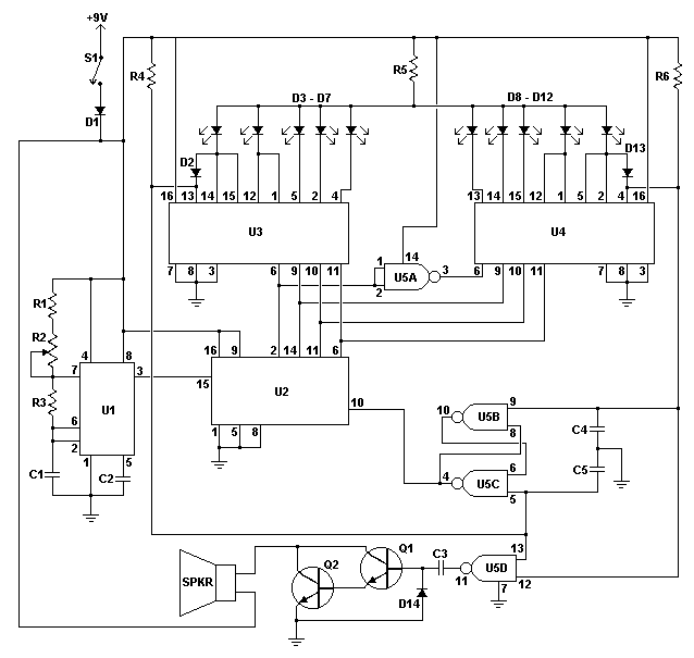
The LED Metronome is a modern interpretation of a classic device which is a staple of music teachers, students and composers everywhere. This circuit uses 12 LEDs to simulate the sweeping motion of the pendulum and a speaker with a simple amplifier to generate a tick as the LEDs at the end of the arc are struck. It is adjustable from about 40 BPM to just over 200 BPM. When made in a Lexan or Plexiglass case it can add a fun ultra-modern touch to music practice (though most music teachers agree that you should never rely on a metronome to keep your beat).

Schematic

Schematic for LED Metronome

Parts

Part
Total Qty.
Description
Substitutions
R1, R4, R6310K 1/4W Resistor
R211.5 Meg Linear Taper Pot
R31120K 1/4W Resistor
R51220 Ohm 1/4W Resistor
C1, C310.1uF Ceramic Disc Capacitor
C2, C4, C530.01uF Ceramic Disc Capacitor
D1, D2, D13, D1441N914 Signal Diode
D3-D1210Jumbo Red LED
Q1, Q222N3904 NPN Transistor
U11555 Timer IC
U214029 CMOS Up/Down Counter IC
U3, U424051 CMOS 8 Of 1 Switch IC
U514011 CMOS Quad 2 Input NAND Gate IC
SPKR1Small 8 Ohm Speaker
S11SPST Switch
MISC1Board, Wire, Case, Sockets for ICs, Battery holder, Knob for R2

Notes

  1. The circuit will reliably run from 6 to 12V. A typical 9V battery will be drained in several days by the LEDs with constant use. A 6V pack made from AA, C or D cells will last much longer.
  2. The circuit will need some calibration before use. Calibration is fairly easy and accomplished by using a stopwatch to count the number of beats. You'll want to calibrate for 60 BPM (one per second), 120 BPM (two per second) and 180 BPM (3 per second). Just use your stopwatch to find the points of R2 that correspond to those beat rates and the mark the dial appropriately. Next find 90, 150 and 210 BPM. By that time you should then be able to evenly mark the remaining positions on the scale.
  3. Blue LEDs need about 5V to light, so if you intend to use blue you will need to remove R5.
  4. For an ideal metronome effect, the LEDs should be arranged in an arc.

Related Circuits

3 Channel Spectrum Analyzer, 40W Fluorescent Lamp Inverter, Fantastic Atom Expander, Black Light, LED Chaser, Simple Colour Organ, TRIAC Light Dimmer, 12VDC Fluorescent Lamp Driver, Infa-Red Remote Control, IR Remote Jammer, LASER Transmitter/Receiver, Light/Dark Detector, Colour (Sound) Organ, Flash Slave Trigger, Strobe Light, Adjustable Strobe Light, LED Thermometer, Electronic Dice, IR Remote Switch, LED Metronome, IR Remote Extender

Comments

Add A Comment

Leonardo
LED Metronome
Wednesday, August 24, 2011 7:28:26 PM
Is there any way we could attach a 7-segment display to the circuit?! I was thinking about putting three displays alined to show the current BPM!
G-DAWG
LED Metronome
Friday, March 19, 2010 12:18:58 AM
works like a charm, if its not ment to work its working
Audioguru
LED Metronome
Sunday, February 28, 2010 10:39:35 AM
Like most projects on this site this one is also missing a very important supply bypass capacitor. The old high current 555 creates a 400mA supply current spike which messes up the Cmos counter unless 100uF and 0.1uF supply bypass capacitors are used. A Cmos 555 could be used since it does not create a supply current spike.
The last 10 comments are currently shown. Show All Comments. Add A Comment

Back To Circuits Page | Mail Me | Search