| Sai |
Electronic Stethoscope |
Tuesday, January 12, 2021 4:49:13 AM |
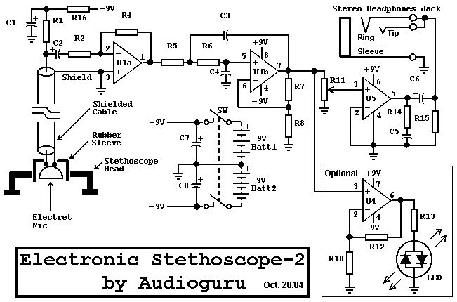
| The Circuit is super sensitive. But i could able to detect the heartbeat at the first stage of amplifier circuit. (i.e near R11). but when i connect the TRS jack to C6/R5 , i could not able to detect the heartbeat and it is completely no sound in the earphones even i have tried tuning the R11 pot.
Could you please let me know why the second stage amplification is failed.
Even in first stage amplification output near R11, i could see the pot is tuned to 2.2k (measured using multimeter between Pot Output pin and ground pin) where i can hear humming effect mixed with the hearbeat signal.
Pl. provide your suggestion on this. |
| Sanish |
Electronic Stethoscope |
Saturday, May 02, 2015 5:57:30 AM |
| Are C6 and C8 wrongly marked? Should their locations be swapped? |
| Amitha |
Electronic Stethoscope |
Thursday, March 19, 2015 8:47:32 AM |
| I made this project, it is working very good . thank you. |
| cheeko |
Electronic Stethoscope |
Monday, October 20, 2014 3:58:59 AM |
| The pin configuration of U1a ,U1b (as shown in circuit diagram) is not right . CAn you please send the right one |
| deepak |
Electronic Stethoscope |
Sunday, February 03, 2013 9:30:11 AM |
| efficient circuit. working good in all aspects |
| jagadish |
Electronic Stethoscope |
Thursday, August 30, 2012 10:44:44 AM |
| sir would u please mention the cost and complete details of this project please..........
|
| abhipsa |
Electronic Stethoscope |
Monday, November 14, 2011 8:50:17 AM |
| We made the stethoscope but instead of LM386 we used LM380 and instead of TL072 we used LM381 as in another book it was written so.. but in our output while using loudspeakers the volume is too low.. we didnt do the volume control part.. we attached an led in parallel wid speaker to check if the circuit is working, the led keeps on blinking but loudspeaker output is too low. also instead of a mic we used a crystal pick-up cartridge. do we need to shield cable the 3 wires from the pick-up cartridge? please respond asap! thanks! |
| mostafa zied |
Electronic Stethoscope |
Sunday, May 22, 2011 12:51:19 PM |
| i made this project and it all is working very good .But replace this mic with mobile phone mic this is very small in size and lower in noise....................thanx |
| chethan |
Electronic Stethoscope |
Monday, April 19, 2010 9:54:55 AM |
| i have done the project.its picking up sound.leds does't match with the heartbeat sound theres lot of buzz sound .and even i have altered it and added a counter to it.it working but the beats are not matching. suggest me something please |
| pranav |
Electronic Stethoscope |
Monday, March 01, 2010 8:21:51 AM |
| i have made the ckt but its not working and i have no idea about the battery which i have made is correct or not |