| Home > RX-7 > My RX-7 > Project Tina > Project Tina, October 1, 2005: Engine Installation, POR-15 Undercoating, ECU Wiring and Battery Box Fabrication |
| Home > RX-7 > My RX-7 > Project Tina > Project Tina, October 1, 2005: Engine Installation, POR-15 Undercoating, ECU Wiring and Battery Box Fabrication |
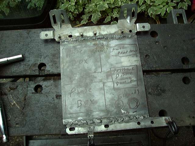
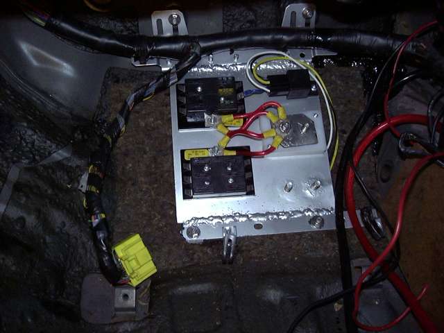
With the installation of the Microtech, the area occupied by the stock ECU becomes free. It seemed like a perfect spot to mount my new electrical panel, so I cut apart the ECU frame and welded in a flat piece of 2MM steel. This would become the base for my new fuse boxes, ground points and +12V distribution block.
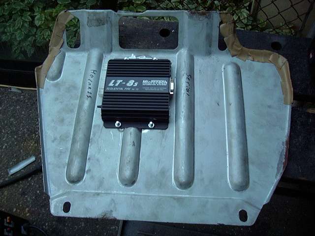
The Microtech LT8s is better then the stock ECU in every conceivable way, including physical size. Thus, I decided to mount my ECU to the underside of the metal ECU cover. Using a jigsaw, I chopped out one of the bulges, then welded in a new flat section of metal. After drilling mounting holes, the ECU was mounted. Clearance is VERY tight between the Microtech and the electrical panel, so I think I will make some 1/4" spacers to move the cover up a little for more room. Still, it's almost as if Mazda had designed the car for what I was doing since everything fits so well.
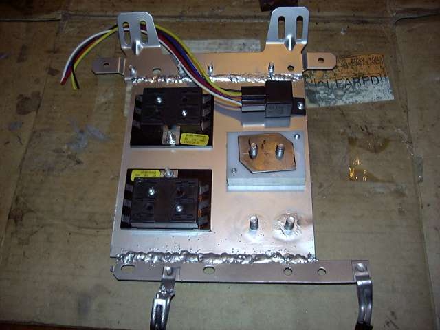
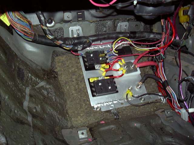
After the panel was cleaned and painted, I laid out the fuse boxes, fuel pump relay and power distribution block. Also notice the two ground studs at the bottom. The power block is something that I made using a block of plastic, two M8 bolts and a little bit of 3MM sheet steel. This was done because I was totally unhappy with the distribution blocks that are available commercially. Most are designed for stereo installations, and while they look nice, their electrical quality is a little questionable (sorry, but one grub screw that you tighten into a 4 AWG wire does not provide enough contact to move 300-400A) and the brittle plastic used tends to crack (at least in my experience). This block is very strong, and since the cables connect with proper lugs, electrically very good as well.
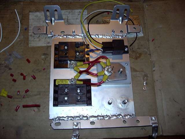
The fuse panels were then wired, as well as the power connection to the fuel pump relay. The wiring to the fuse panels is a bit of overkill, but since this is the only path for power to the engine, I wanted to assure good connections with little voltage drop. The dual 8 AWG jumpers were coated in dielectric grease before being crimped down, and the studs afterwards were thoroughly slathered in grease before and after being tightened. This will prevent any corrosion as the interior of a car is actually a very moist environment. I use dielectric grease on every single connector.
Two fuse boxes are used to separate the engine bay circuits from the interior circuits. The stock fuse box is still in place, this box just provides power to all the "extra" stuff. The top box feeds the engine and supplies power to the ECU, ignition, e-fan, fuel pump and relays. The bottom box will be for audio, gauges, foglights, horns, etc.
It was now time to start running the harness for the Microtech. The stock engine harness had already been stripped down to contain only the wiper, alternator and water temp wires, so the Microtech harness was passed through the stock rubber boot and into the interior of the car.
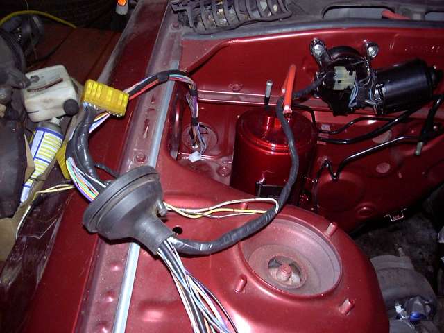
The Microtech harness was then laid into place roughly. When I wire standalones, I like to roughly lay the harness where it should go and then bring out leads to each sensor and connection. I then loosely tie with wire ties and start making the connections. After the harness is wired, the sensors check out and engine starts, I then neatly loom everything in the appropriate harness wrap.
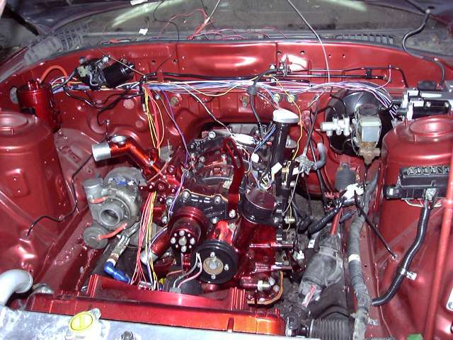
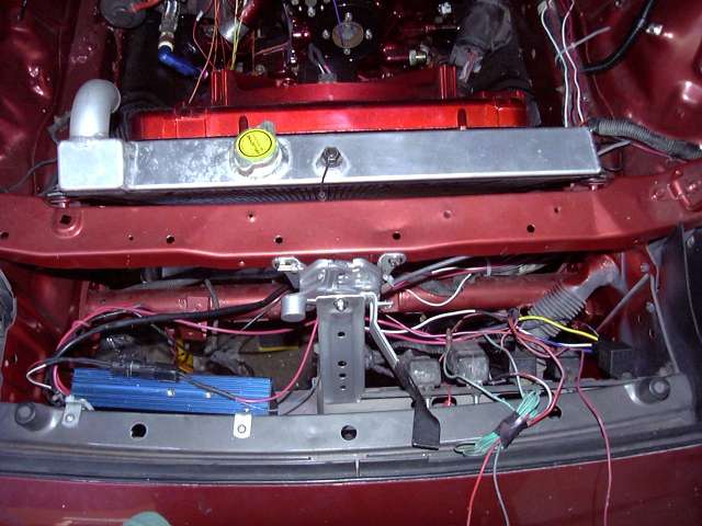
With the harness in place, the actual wiring can start. Shown here is some of the wiring to the Crane HI-6 ignition box, and the electric fan relay (far right). The Microtech harness is short, so the leads to the ignition and fan needed to be extended. I ran them along the stock body harness after they lead accross the firewall, over the brake booster and underneath the trailing coil. The Microtech's auxillary output is being used to control the e-fan in my case, but it will also run almost anything you can think of (idle motor, boost solenoid, nitrous, microfueller, etc.). Note the modern WeatherPack style connector used to connect the ignition box. These connectors provide a totally weather tight connection and are vasty superior to the connectors that came with the FC. But they are certainly not cheap. The jumbled mess of wire near the relays is the old foglight wiring, which will be trimmed and set up properly later on.
Here you can see the beginnings of my engine bay harness along the stock body harness, as well as the wiring to the leading coil. The orange and black wires are from the Crane box, and as you can see the stock igniter is totally bypassed. It's function has been superceeded by the Microtech and Crane box, so it's only purpose now is as a place to mount the leading coil.
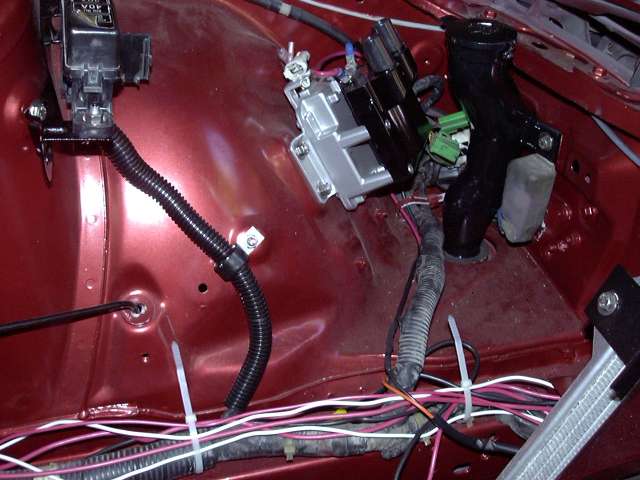
This is a rather poor image of the wiring around the trailing coil. Two more WeatherPack connectors have been used, a single (hidden) and a triple (visible). The triple is the ONLY place the Microtech harness connects to the body harness. It contains the pink 12V ignition wire, and the select and trigger wire for the trailing coil. The single connector is tied to 12V ignition as well, to turn the Crane box on. I decided that I would rather use two connectors instead of a quad connector for organization purposes. It may look messy now, but once I know everything works it will get tidied.
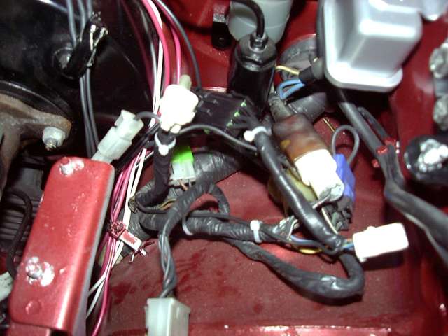
Time to wire the primary injector connectors. First, each wire is stripped about 1/2" from the end. Adhesive lined double-wall heatshrink is slipped over the wire, then the stripped leads are twisted together solidly, then the joint is soldered. I am super anal about my wiring. In a sense, I view wiring as sort of an art and thus try very hard to make it as perfect and reliable as possible. This means NO CRIMPS unless they cannot be avoided, no electrical tape, always new connectors (if possible), and intelligent wire routing and looming. I put large amount of thought into how each wire is to be run and connected to avoid having to cut or splice it later. To be perfectly honest, I have NEVER seen a wiring job done by someone else that I have been happy with.
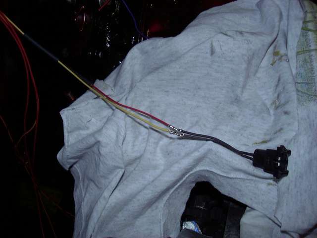
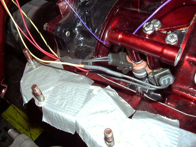
After they are soldered, heat shrink tubing is used to insulate. I only use double walled adhesive lined shrink tubing for this. It costs about 3x as much as "regular" tubing, but is about 10x stronger. The adhesive lining seals the joint permanently, and adds a lot of strength to the connection. Because of the adhesive, it is almost impossible for water to penetrate and thus you will never see corrosion at the joint like most harnesses (even OEM harnesses) have. Those injector connectors are the modern WeatherPack version of what was used by Mazda. They are sealed both at the injector itself, and at the top where the wires enter.
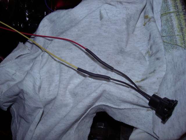
Here are the completed injector connections. You can't easily tell from the picture, but the wires to each injector are exactly as long as each other. The red wire on each injector faces the rear of the car, and the heatshrink has been staggered between injectors as to not cause bump in the harness.
Now back inside the car, some wiring takes place at the electrical panel. Again, it's pretty messy right now, but will get cleaned up when the harness is finalized. The thick red and black wires are the battery cables. They are 4 AWG cables (4 AWG is a little thin actually, I recommend 2 and bigger) that lead back to the passenger storage bin. On each end, the appropriate lug has been installed and soldered in place. I prefer to solder these lugs even though I have the proper (and expensive!) crimper. I just feel that it is a more permanent connection. Again, the connections were covered with adhesive filled heatshrink, then the appropriate colour of heatshrink was used to make them a little more visually appealing. The red heatshrink is just single wall stuff, so all it's good for is aesthetics anyway. The thinner red wire is from the alternator. In the final configuration, it will connect through a circuit breaker. The two black wires are ground for the ECU and fuel pump. On final connection, the paint will be scraped down to bare metal and dielectric grease will be applied.
Since the battery is being relocated, a battery box is needed. Most people seem to use those plastic boxes available at auto/marine stores, but I have never been happy with them. They're very flimsey, and would basically do nothing to stop a battery from becoming a 50 LB+ projectile in the event of a collision. Even though the battery is supposed to be strapped or tied to the car, this is rarely done correctly either. NHRA (and I think SCCA?) rules specify that the battery is to be secured to the car, and not the battery box. Thus, I decided to build a sturdy battery box which has mounts that will also serve to secure the tiedown strap to the car. The first step was to measure the battery (an old Optima was used as a guide) and cut the angle iron to size.
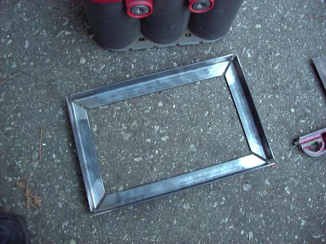
The box was then welded together....
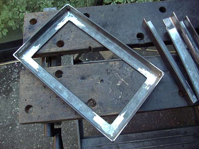
...and corners were installed.
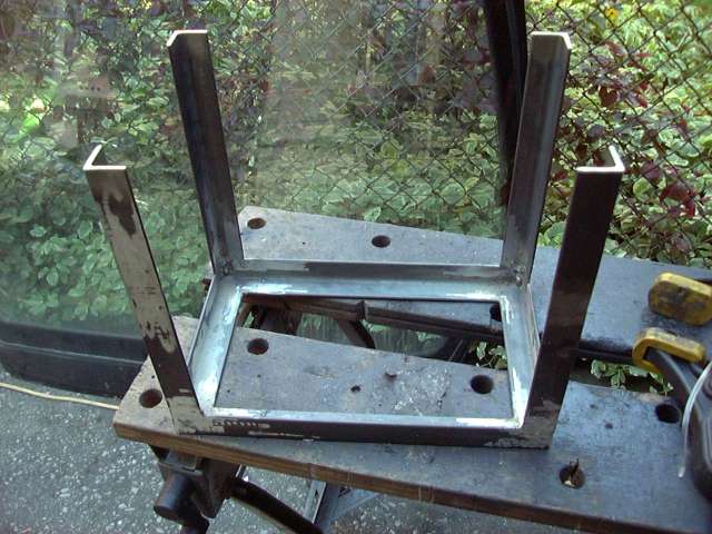
I finished off the box by welding some 1.5" wide strips at the top, and then ground down all the welds.
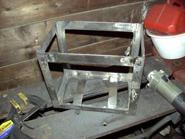
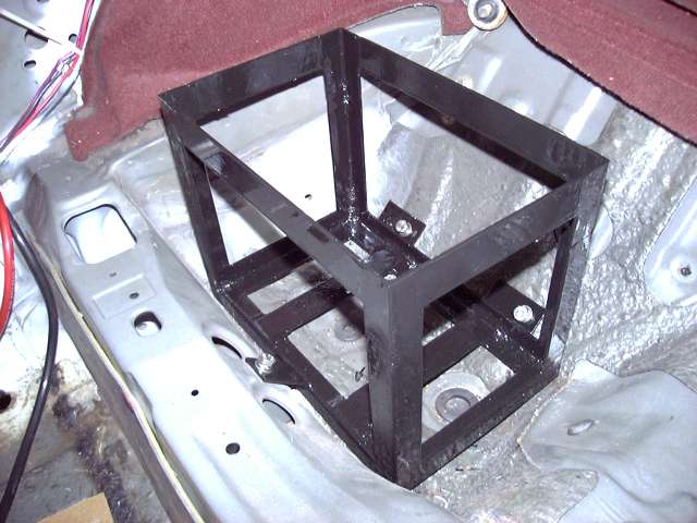
Once mounts were welded on and the box was painted with POR-15 (it's resistance to acid makes it perfect for the job), it was bolted into the car. There are three mounts; one at the front and two in the back. Each attaches with an M8 x 1.5 stainless bolt.
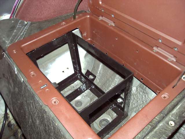
Some trimming of the stock storage bin lid was required as well as removal of the fabric "bag". The lid still closes fully and locks.
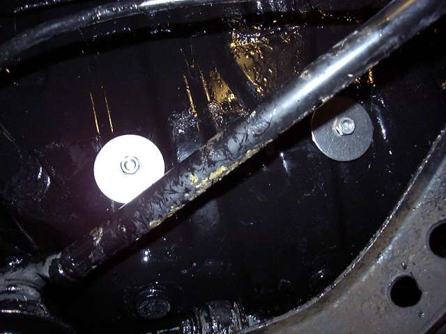
Finally, here's the underside of the car. Large stainless washers were used to distribute the load of the box over the thin metal of the underbody. Note that this is just a mock-up for picture purposes as I didn't have bolts long enough to fit the lockwashers. There is rust and gunk on the suspension arm since I didn't bother painting them.
And that's about it for now. Next major task is to build the upper intake, but I'm saving that until I can post a thread which can cover the entire process. After the intake, there's the starter, ground and battery wiring, the secondary injectors, intercooler piping, TID, etc. It's getting closer and closer to being started. However, that will not take place this year. The cold weather is starting to roll in, and we will probably see show in late November. I'm not going to rush myself to get it started only to have to put everything away for the snow. That's OK, since it means that the car will start in late spring, which will give me the entire summer to break it in and then install the big turbo.