| Home > RX-7 > My RX-7 > Project Tina > Project Tina, August 4, 2004: Assembling The Engine, Modifying Lower Intake Manifold |
| Home > RX-7 > My RX-7 > Project Tina > Project Tina, August 4, 2004: Assembling The Engine, Modifying Lower Intake Manifold |
OK guys and gals, here's another chapter of my Project Tina build. In this episode, we put together the half-bridge turbo-NA engine.
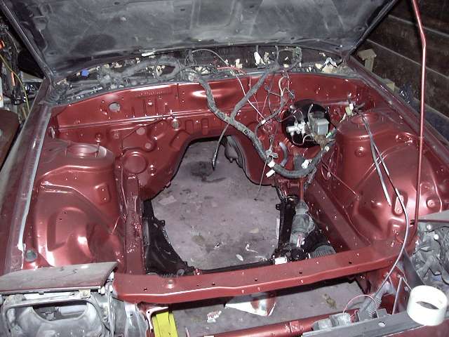
When we last left our intrepid hero (OK, I'm stopping with the comic book narration now), the engine bay had just been given a quick coat of Cherry metallic, and it was time to actually assemble the engine that would live there.
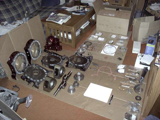
Laid out here is every hard part, gasket and seal required to assemble one 13B short block. Everything has been given it's final cleaning, and it's all organized with clearly written labels to avoid confusion during the build.
Here's the rotor assembly area. A clean space is needed to install all the necessary seals on the rotor beforehand. It's a time consuming procedure, and you don't want to stop a build everytime you need a rotor. You can also just barely see a note written in marker that says "Apex corner seal towards intermediate". This is to remind me that the corner apex piece must face the center of the engine to prevent them from falling through the eyebrow port.
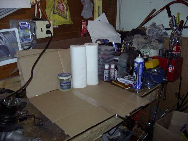
The oil o-rings were first assembled. The rings are coated with Vascelene and then rolled into the metal carrier. This must be carefully done to avoid twisting the rubber ring.
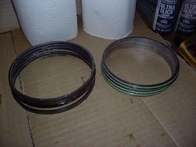
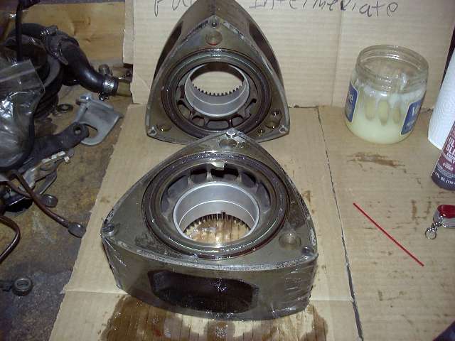
Sorry to skip so many steps, but I just went ahead and assembled the rotors without bothering to take too many pictures. Vascelene is used to hold everything in place, and it's a pain to clean your hands every step to take the picture. Essentially, the oil springs are put in place, then the rings themselves. I then install the corner seals, then the side seals, then slide in the apex seals (leaving out the springs). Everything is then covered in Vascelene to keep it in place. I also prelube underneath the oil rings with assembly lube.
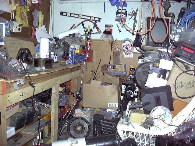
Here's a general picture of the work area. Yes, it's quite messy. I have 24.5 years of valuable junk stored in that room.
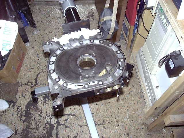
The front iron mounted on the engine stand. I would certainly recommend an engine stand to anyone doing this. Yes, it could be done on a table or bench, but it would be a major pain in the butt. A stand allows you to easily rotate the engine, and move it around as necessary. I got my engine stand adapter from CP Racing. They build them in house out of thick steel, and much cheaper then Mazdatrix.
First, the front stationary gear gets installed snugly with 1 bolt. It's an interference fit, so the gear must be pushed in exactly perpendicular to the iron. Assembly lube around the outer circumfrence helps greatly.
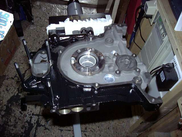
Here, the coolant o-rings are installed. They are first covered with Hylomar (a non-hardening, non-drying gasket dressing/sealant) and then pressed into place. The black o-ring goes in the outer groove (make sure the white mark is NOT facing top or bottom) and the red/green o-ring goes in the inner groove (place the joint in the ring above the intake port). The hylomar holds everything place and prevents horrible o-ring pinching (a sure way to make a water pumper).
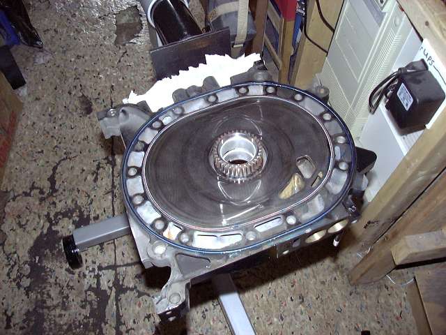
The front iron is now pre-lubed with engine assembly lube, and is ready to have the eccentric and front rotor installed.
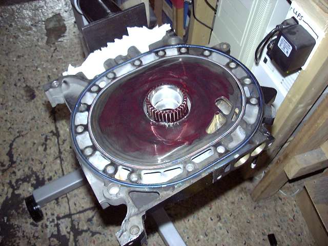
To install the front rotor, it is placed so that an apex points down and all apexs are within the proper running area. The gear is then meshed with the front stationary gear. Really, it only fits one way.
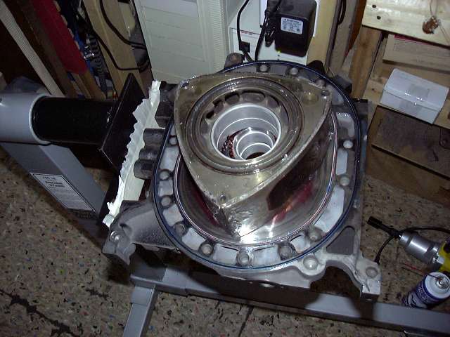
An extreme closeup of the front rotor bearing and stationary gear after things have been thoroughly covered in assembly lube. You can never lube too much, especially if the engine will be sitting a while before starting (as this one will).
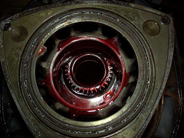
The eccentric is then carefully lowered into place after all bearings are lubed. You don't want to make the shaft slippery because it's too easy to drop.
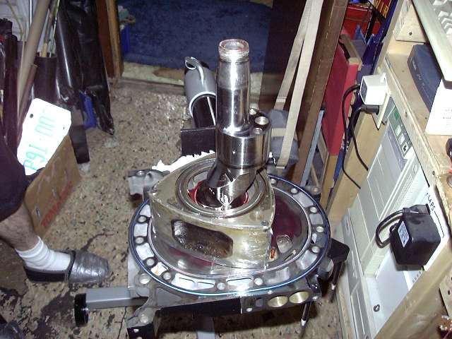
After the extra hylomar was cleaned from the "legs" of the iron....
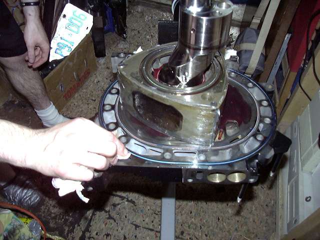
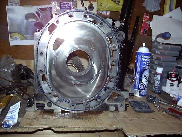
...it was time to place the front housing. Here you see the housing with it's mating surfaces coated in hylomar. BTW, hylomar makes a huge mess, so keep plenty of paper towels ready.
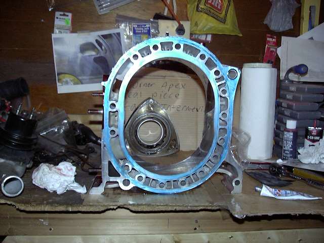
Sealant is needed on the legs of the iron. The Renesis seems to have grooves in this place to hold the sealant more effectivly. Us 13B people just have to hope we don't get oil seepage.
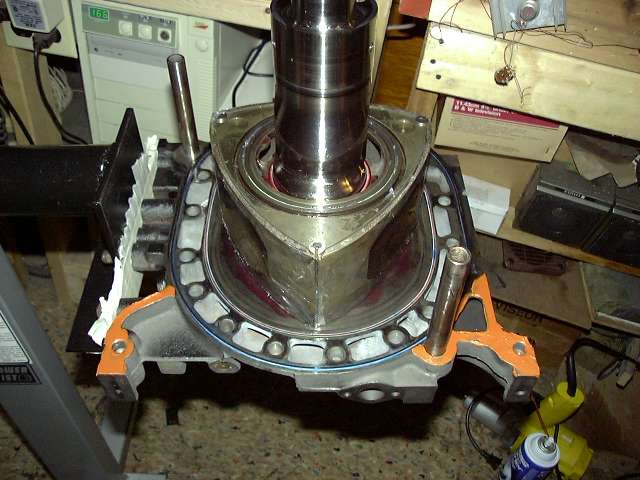
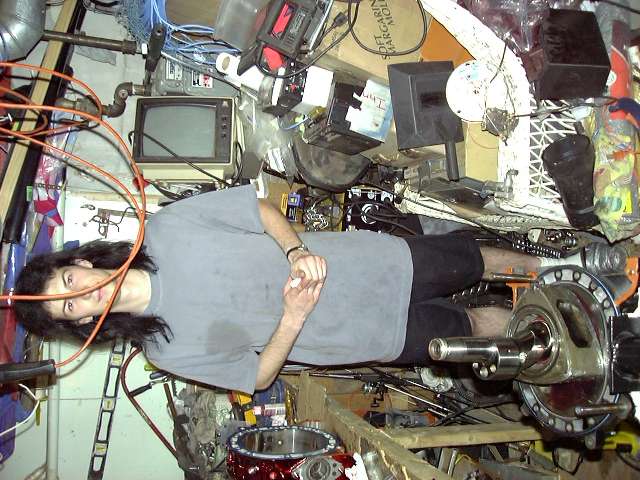
Installing the front rotor housing over the dowels. This is the process of building a "Dagwood sandwich". Note slight lube on the dowels. Makes it easier to slide the housing down.
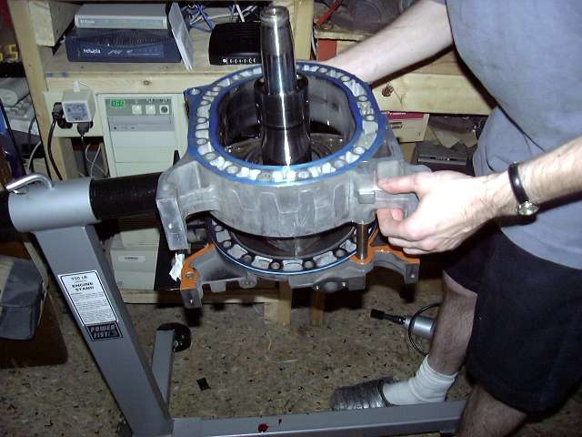
The front housing is installed. Now, the apex seal springs need to be inserted. This is done by removing the corner seals, then pushing the apex seal springs in. The small one goes in first and gets pushed as far as it will go, with the aid of a pick. After that, the large spring is pushed in until it "clicks". This click is made by the smaller spring self adjusting, and the large spring going over the bump on the apex corner. Contrary to what most people think, the mouth of the apex seal spring faces TOWARD the seal, not toward the rotor. Now the corner seal is reinstalled.
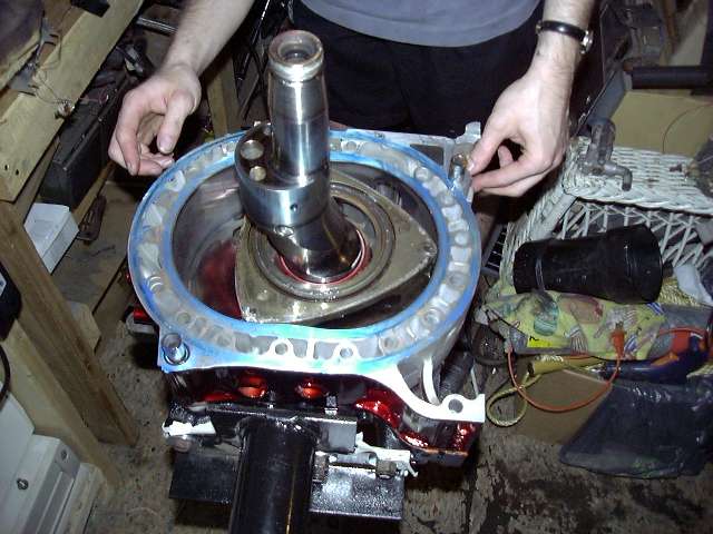
A close up of the rotor showing the apex seal, corner seal and assembly lube.
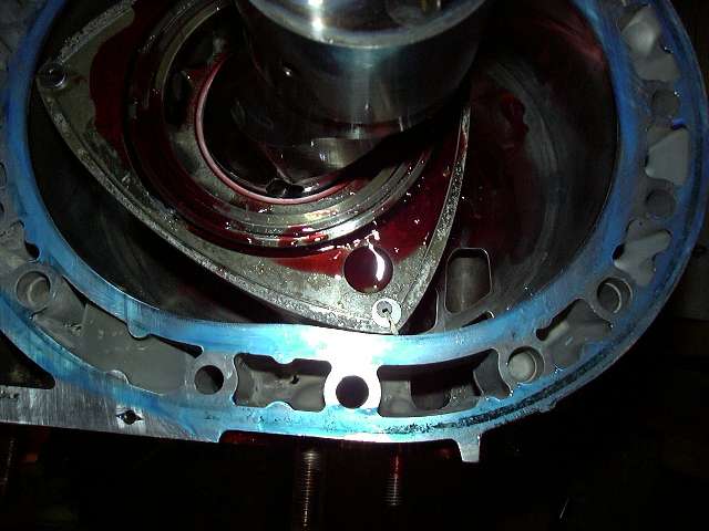
Another closeup showing the ports and how the eyebrow looks against the housing. If I had been thinking, we would have rotated the rotor to illustrate how early a bridgeport opens compared to stock.
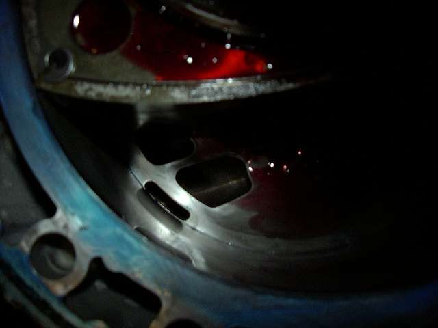
The intermediate is clean and ready to go. The shadows and flash make the primary ports look pretty crappy, but they're decent. I could have actually gone larger.
