| Home > My Projects > Rotary Engine Eccentric Shaft Lamp |
| Home > My Projects > Rotary Engine Eccentric Shaft Lamp |
Date Of Project: Fall 2004
The eccentric shaft in a rotary engine is a bit like the crankshaft and camshaft in a piston engine combined into one piece. It is the shaft on which the rotors rotate on a lopsided orbit, moving them around the chamber to accomplish the 4 strokes of combustion. Rotary Engine Illustrated explains it properly in their very informative website. How this eccentric shaft was reborn into a lamp is a bit of an interesting and long story. However to make a long story a bit shorter I will summarize.
In the late fall of 2003 a friend of mine had an engine built by a Toronto area shop for his 1987 Mazda RX-7. Tony chose to convert the car from naturally aspirated to turbo and decided to do everything correctly. Unfortunately this local shop (who will not be named) did not. After battling with near constant problems for several months, the engine finally seized solid after driving only 1000 KM. Tear down of the engine showed us that nearly everything was done incorrectly but the last nail in the coffin was that a bearing had been allowed to slip out of place, get ground up and thus spread metal filings throughout the entire oil system. For those who know rotary engines, the bearing in question was the torrington bearing. In a classic error that should only be made by the most inept rookie builders, this bearing fell behind the spacer due to incorrect assembly order, was crushed when the front nut was torqued down, and the rest was history. Every bearing in the engine was spun, the eccentric shaft was destroyed, the stationary gears totalled and even the oil pressure regulator turned to complete junk (fine metal filings jammed it solid). After some soul searching we decided to bite the bullet and rebuild the engine, replacing the damaged parts with new. After several months of weekend work (we had to redo almost everything, including the absolutely pathetic port job done by the previous builder) the new engine fired up first try and has been running strong since.
During this entire experience both of us went to some dark places at times. One of the ideas we came up with for some humorous revenge was to create a lamp out of the damaged engine parts and then ship it to this unnamed shop postage-due as a gesture of thanks. And thus, the eccentric shaft lamp was born.
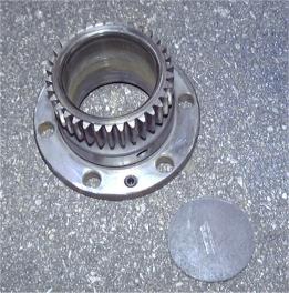
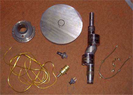 The main parts of the lamp were already provided by the seized engine: front and rear stationary gears, eccentric shaft and eccentric shaft bolt. The remaining parts were purchased separately. Since this was to be shipped at the receiver's cost, weight was an asset so the first stop was the metal store where I purchased a circular steel base approximately 11.5" in diameter and 1.25" thick. Made out of a very dense steel it is nearly 70 LBS in weight! In addition to the hard metal parts some lamp equipment was purchased at a local hardware store. This consisted of the appropriate socket, shade holder, cord and plug.
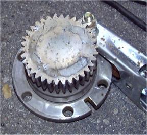
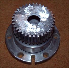
Once the parts were gathered it was time to begin assembly. I started by finding the center of the base plate, marking it clearly and welding the eccentric shaft in place vertically. Prior to welding, the rear stationary gear was slipped over the shaft and suspended over the area to be welded. It took a little bit of fiddling to fit the welding torch underneath to get a good weld. If I had been thinking I would have stick welded it since that process requires much less clearance then the wire-feed flux core process I was using. When the eccentric shaft was fully secure, the stationary gear was lowered and attached to the base using the actual bolts that previously held it to the engine. The bolt heads were welded to the base and the threaded shank welded to the stationary gear. The idea was to run the lamp cord up through the hollow shaft so it had to pass through the stationary gear (using the stock oil passages) prior to welding.
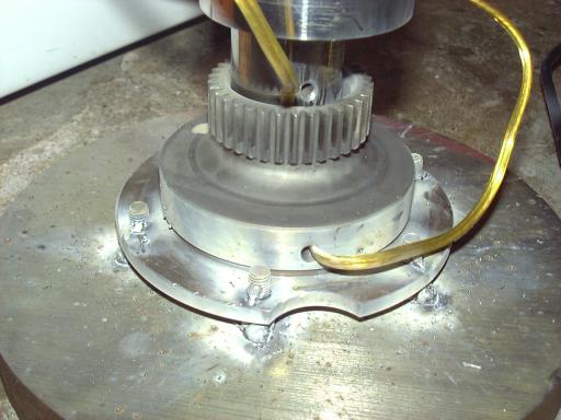
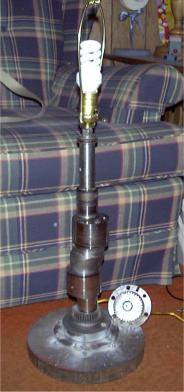
With the base complete some method to control the light was needed. As luck would have it I was at the local electronics store for an unrelated project and happened upon a small 120V key switch. What a perfect addition to an automotively inspired lamp. So I snapped it up and then proceeded to make a base for it out of the front stationary gear. This involved cutting a small circular section out of sheet steel, welding it in place, grinding it smooth and then mounting the switch. The look was perfect, much better then the typical lamp switch.
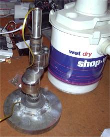 At this point the small dilemma was realized. It was going to be almost impossible to draw the thick and stiff lamp cord through the center of the eccentric shaft. I tried using a thinner stiffer wire as a fish, an actual fish and basically just forcing it. But after wasting about an hour I remembered how I sometimes draw wires through long and complicated conduits at work. Often electrical conduit has so many bends and internal ridges that an electricians fish will get stuck or jammed. The trick is to put a vacuum on one end and suck a piece of string through, then pull the wire through on the string. Well, that's exactly what I did in this case. A Shop Vac provided the suction and the cord was easily drawn through on the string. A little cable lube was needed to make the process easier and to avoid tearing the insulation.
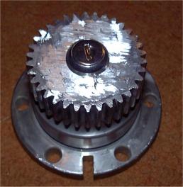
 To mount the bulb holder some method of attachment was needed. The holder screws onto a small hollow threaded rod though which the cord passes. The stock eccentric shaft front bolt seemed like the perfect choice so a hole was drilled through the middle and the threaded rod epoxied in place with JB-Weld. This particular eccentric shaft bolt took some serious abuse as shown by the mushroomed head. The shaft was originally so stuck in the seized bearings that it took multiple hits with a 25 LB sledge hammer to loosen it. When the shaft came out the bearings (made of bronze with a babbit coating) were welded to the shaft and had to be slit down the center and heated with a torch to allow removal! Too bad we had to remove them because they would have made the shaft much more dramatic with evidence of the failure.
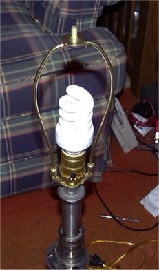
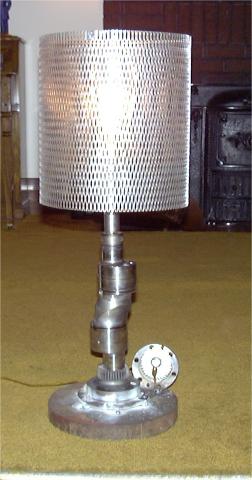
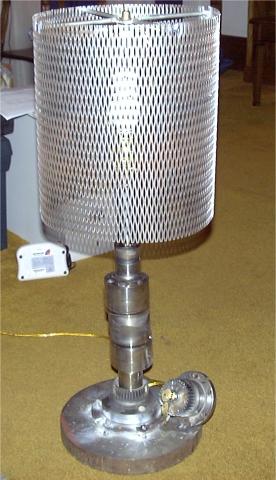
The key switch assembly was installed, as was the bulb socket and shade bracket. It was then time to actually make the shade. It was constructed primarily out of an expanded metal mesh what was shaped around the base as a circle. Welding thin metal mesh is an interesting exercise since because the mesh has such little heat capacity it is very willing to burn through. Only small tacks on the lowest current setting can be made and even then I burned through several times. The top bracket was made by welding 4 short sections of round bar to opposite sides of a large washer. I lined it up mostly by hand and was happy how nicely it turned out without any measuring.
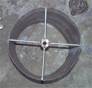
While it turned out how I had imagined, a smaller mesh is needed inside of the shade as the large holes in the expanded metal can kind of make it an un-shade if you look directly at the bulb.
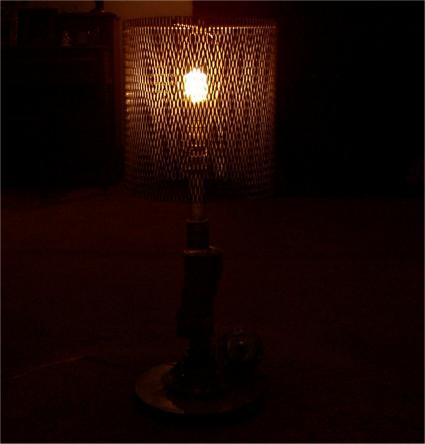
Overall I'm very pleased with how the lamp turned out. In fact I've been so reluctant to actually give it up that it currently sits on the corner in my bedroom on the corner of my dresser. While it's very heavy (final weight is over 90 LBs) it's a very functional piece of furniture. There's also something totally satisfying about turning on and off the lights by twisting a key!