| Home > My Projects > Mini 12V Air Compressor |
| Home > My Projects > Mini 12V Air Compressor |
Date Of Project: December 2010
One of the most useful tools when repairing computers is a source of compressed air. Air is really the only thing that will clear out dust encrusted fans, remove lunch leftovers from keyboards, and get rid of all the spilled toner from an off-brand refilled toner cartridge. The problem is that compressed air doesn't travel very well. At the work bench, the compressor is always near by. However on the road, one must rely on those expensive cans of air (actually most are tetrafluoroethane or difluoroethane) and those things, well, kind of blow. They don't have the flow or pressure of a proper air compressor and don't last long at all. It isn't uncommon to go though a whole can while cleaning out a large laser printer. One option is to fill a portable air tank but let's face it, those things are huge and not something I'd like to carry around. Another is to carry a small mains powered air compressor but that has the same disadvantage as the air tank; size and weight. Plus, there has to be somewhere to plug in.
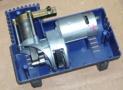 There are portable 12V air compressors available on the market. They are, however, designed to be mounted in a vehicle for things like air suspensions, locking differentials, and service truck use (inflating tires, running air tools) and thus are still rather large and not exactly portable. They also require quite a bit of battery power to run. The obvious choice for a battery powered portable compressor then seemed to be a tire inflation compressor. Everyone has seen these and if you own a car, have probably used one at some point or carry one around in the trunk. They are cheap, capable of achieving about 150 PSI of pressure (most are advertised at 250 PSI...which is optimistic to say the least) and quite small. One had been sitting on the shelf in my basement for a while after being retired due to a broken cord so I opened it up and found exactly what I was hoping to see; a tiny compressor pump.
The pump looked to be the perfect heart for a small compressor. While these pumps can develop some decent pressure, their small displacement means that they can't really move that much air with every stroke. Running the pump and then pointing the output hose towards a fan clogged with dust doesn't exactly blast the dirty in every direction. It kind of just sways in the breeze. Still, the pump was a starting point and I just needed to build the rest of the compressor around it.
I started by first removing all the extra plastic around the pump mounting area to form somewhat of a cradle that would be easily attached to any sort of fabricated base. The astute readers by now have probably noticed that this is a different pump than the one pictured at the top of this article; more on that later.
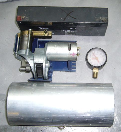
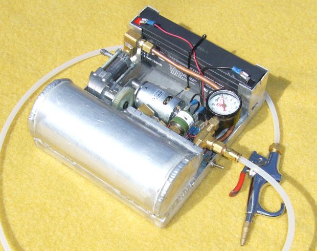
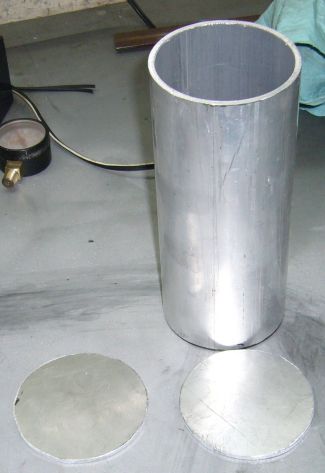
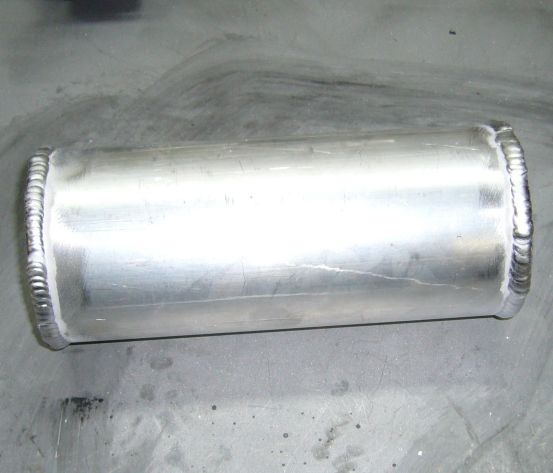
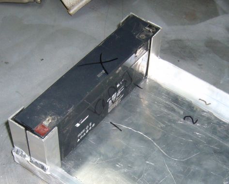
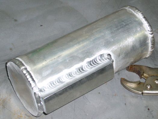
The battery is a 12V 2.3 AH sealed lead acid gel cell of exactly the type one would find in small UPSs, emergency lighting and security systems. I used it as a basis to set the width of the chassis which is just about 7 1/4" (the battery is 7" long). I also cut a piece of 3" diameter 1/8" wall aluminum tubing to 7" as well. This will form the air tank. The gauge is just a spare off of an old compressor regulator that was sitting around the shop and has a 1/8" NPT pipe thread.
Next, end caps were cut for the air tank out of 1/8" aluminum. I did those freehand on the band saw so even though they are a little uneven I think they turned out pretty well considering. The ends of the tubing were beveled with a grinder to assure adequate weld penetration and then the caps were TIG welded in place. Pressure vessels scare the hell out of me. Homemade pressure vessels are even worse so I wanted to be sure that my welds were not going to be the weak point. Aluminum doesn't have the elasticity of steel (I dare you to measure the circumference of your compressor tank empty and then again when full) so afterwards the whole tank was annealed with a torch to help remove the embrittlement that welding can cause.
 |
 |
The chassis was then built by first making a frame of 3/4" by 1/16" aluminum angle. It was kept straight during welding using a 90 degree welding vice and allowing each weld to cool before being removed from the vice. With the frame complete I then traced it out onto a sheet of 1/16" aluminum, cut out the resulting bottom piece, and then welded it in place. There was some warpage even though I kept the heat low, welded in opposing 1" beads and used thin filler but this was easily corrected after it cooled by a little hand straightening.
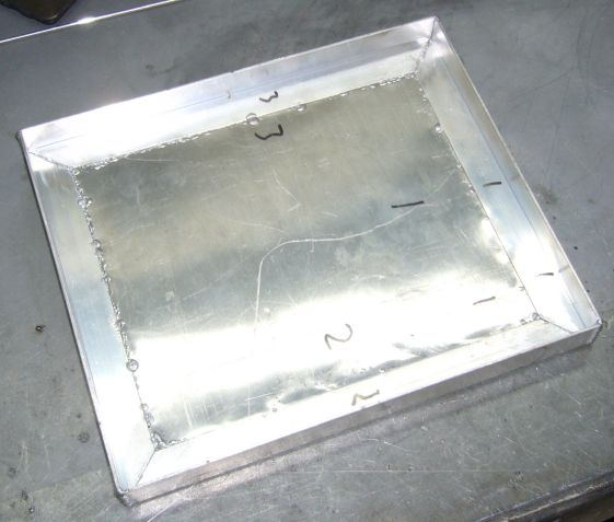
Next up were the battery holders which were made of the same material as the chassis, cut to 2.5" lengths and welded into the corners of the frame.
The compressor pump has two outlets; one for the air line and another for the gauge. I had no use for the air line outlet so I first attempted to weld it shut. I say "attempted" because as soon as I struck an arc, the metal blew away in an odd haze of green. Clearly I was dealing with low grade and unweldable "pot metal". Luckily I had only damaged a small section of the barb so I just ran an M5 tap down it, then screwed in an M5 bolt thoroughly coated with JB-Weld epoxy.
I needed to get air out of the pump through the previous gauge port. This gauge port looks like 1/16" NPT, smells like 1/16" NPT and even tastes like 1/16" NPT, but it is not 1/ 16" NPT. In fact, the hydraulic shop didn't even have a single fitting in stock to match the threads and we couldn't find a similar thread on any of their charts. So as far as I can tell, whatever thread was used was just made up by the Chinese factory that built the pump and doesn't really exist. To get around this, knowing that I couldn't weld on a new fitting, I just cut the bottom fitting from the gauge that came with the original compressor. The gauge face and dial had been smashed a long time ago so it really wasn't much use. I then drilled the gauge stub out a little bit, screwed in a 1/16" NPT to 1/8" NPT adapter, and then soldered it in place. And then of course promptly had to redrill hole through the center as the solder had clogged it. It's too bad that this effort to make a custom fitting was ultimately wasted as this pump wouldn't end up on the finished compressor.
To connect fittings to the tank I needed some kind of manifold. I didn't want all those fittings sticking out of the side of the tank (where there would have been space to weld in bungs or simply drill and tap) so I decided to create a manifold area on the inner tank side. I welded a 4" length of 1" x 5/8" aluminum flat bar to the side of the tank, positioning it so that it would just barely fit beside the compressor pump.
At this point all the major fabrication was done. I drilled three holes in the manifold and then tapped them to 1/8" NPT, after which I welded the air tank to the chassis. Once in place, I began installing the fittings. The main air feed into the tank is via a length of 1/4" nylon tubing which connects to the compressor pump outlet. Because space is limited (the compressor motor also occupies this area) I used a 90 degree 1/8" NPT fitting to point the releasable tubing fitting to the side and down a little. It tucks just under the 145 PSI pressure switch. The pressure switch is an Air Lift 24551 switch used in air suspensions. It has a 100 PSI on point, and a 145 PSI off point. It's actually made by WILSPEC and used in many different industries.
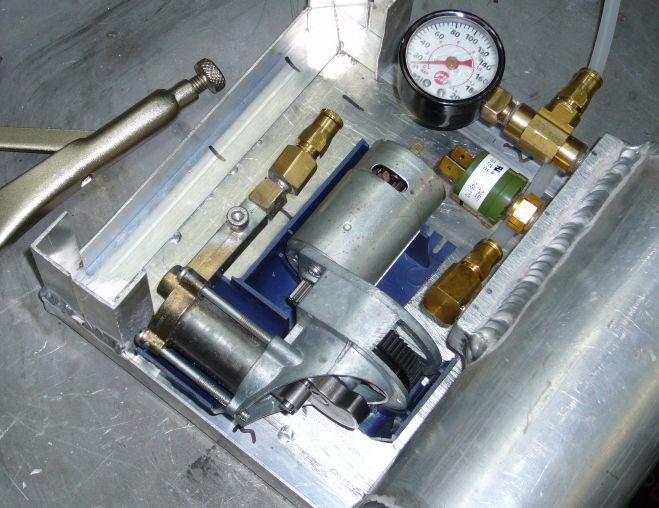
The pressure switch is mainly just a safety measure. In reality the little compressor pump isn't sealed internally well enough to push 145 PSI. To the right of the pressure switch, a simple 1/8" NPT T fitting allows connection of the pressure gauge and the air takeoff feed to the blow gun. The compressor pump is secured to the bottom of the chassis with two screws bolted to the underside, which are hidden under the motor.
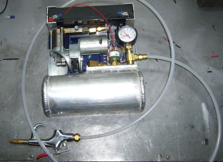
With the main mechanical assembly completed the blow gun was then attached using an length of tubing approximately 3 feet long. The tubing which connects the pump to the tank kind of snakes underneath all the fittings and around the relay. Controlled by the pressure switch, the relay switches on and off the pump. The relay is necessary because the pressure switch contacts are only rated at around 1A and would quickly burn out when used to control the pump directly (the pump draws about 4A). A power switch, hidden in this picture underneath the T fitting, cuts power to the whole circuit directly at the battery.
The compressor was now complete! I threw the power switch and the pump sprang to life. Figuring that it was either going to work perfectly or flat out explode, I watched from a safe distance from behind my safety glasses. As the gauge rose past 100 PSI to 110, then 120, then to 130 PSI, I waited for the pressure switch to cut power to the pump. Just as the gauge reached 140 PSI, there was a loud "HISSSS...PFFFFFTTTT...RATTLE....HISSSSSSSSSSSSS" that I must admit, nearly made me have to seek a change of underwear. Quickly cutting power I expected to see a broken weld seam, burst fitting or split hose. What I found was a bit more annoying.
On top of the cylinder head, a plug had blown out. It seems that this plug closed the chamber in which the outlet check valve was located. As either some kind of cost saving or safety measure (I'm assuming cost saving) the factory secured that plug with retaining compound. The 140 PSI had caused this compound to fail, blowing the guts of the check valve out and instantly releasing stored pressure from the tank. So yeah, when these little compressors advertise "250 PSI Maximum Pressure" on the box, picture this little plug held in only with glue. By some miracle I was able to find the check ball on the floor of the shop. A few days later I removed the pump, reinserted the check ball and spring, then epoxied in a pipe plug after tapping the hole for 1/8" NPS. It worked, sort of, but never really did make much pressure after that. The incident must have blown out the piston seal as well.
 There didn't seem to be much point wasting any more time trying to make this pump work because it was already at least 10 years old and any auto parts store carry these small tire inflators for under $20. In fact, I received a Canadian Tire flyer the next day advertising a tire inflation compressor for $9.99. After picking one up in the store and taking apart the case as soon as I got to work, I wish I had gone this route in the beginning because wouldn't you know it, the damn gauge port is 1/8" NPT! This time the gauge mounted directly to the cylinder head and also functioned to retain the check ball and spring. It was trivial to just unscrew the gauge and then screw in a 90 degree 1/8" fitting. Of course, the original hose outlet needed to be plugged in the same way as the old compressor by tapping it out then threading in a screw sealed with epoxy.
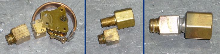
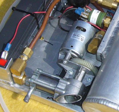
Even though the new pump was a bit smaller than the original, it just barely fit in the existing space due to the fittings being relocated to the top of the cylinder head. I ended up having to use two 90 degree fittings in the sort of odd arrangement just because of the way the threads were cut on the cylinder head. I couldn't get the bottom 90 degree to be tight enough not to leak unless it was pointed directly up so I had to use another 1/8" 90 degree elbow to get the air pointed in the correct direction.
You'll notice also that the nylon tubing has been replaced by copper line. From science class, we all know that compressing air heats it up and that's exactly what caused the nylon line to fail after a few minutes of operation. After watching the nylon tube blow out twice I decided that copper is the way to go. It took a little bending to snake the 1/4" copper tubing around all the fittings and the relay but aside from that it was an easy retrofit and should have been used in the first place.
So how well does this little compressor work? For its intended purpose, it works quite well. It takes about 30 seconds to pump up to 120 PSI, after which it will deliver between 3 and 4 quick bursts of air before it needs to fill up again. The pump never does make enough pressure to turn off via the pressure switch which is OK by me as internal leakage in the pump's check valves would just cause it to turn on again a few seconds later. These little pumps really are poorly made and quite leaky. As for runtime on the battery, about 5 solid minutes is generally more than enough for several uses a day followed by a recharge when I get home in the evening. Obviously it's not going to run air tools, but it could inflate a tire if necessary. As a source of air for cleaning out electronics equipment, it does the job admirably. And as a bonus, it hasn't blown up yet.
I have a video of the compressor in operation on YouTube for your viewing pleasure:
Please read the following FAQ before emailing me about this project. It may answer your question. The FAQ is updated based on common questions I receive via email.