| Author |
 Topic Topic  |
|
Zogpy
New Member
2 Posts |
 Posted - Feb 11 2012 : 5:29:35 PM Posted - Feb 11 2012 : 5:29:35 PM


|
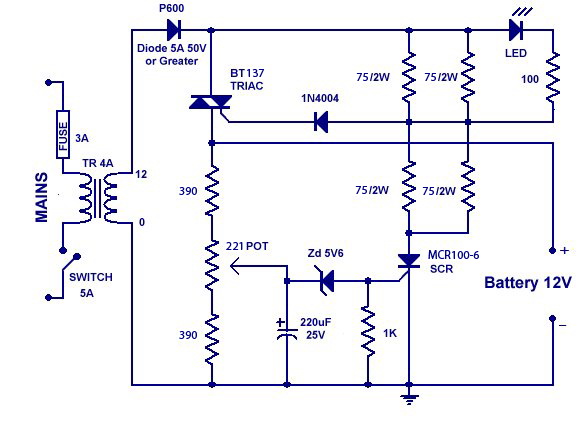
Hi Aaron, I have a problem with this circuit, I only get 7-8 volts output. The Led is always on I need your help, I could not find the exact values for some parts like the Triac, I used BT137, 390 ohms resistors instead of the 330, 75k ohm 2w resistors instead of 82k, 221 ohm pot, MCR100-6 instead of the Brx49. I feel so disappointed, & I wish to get this charger to work. can you plz tell me what might be causing my problem.
 |
Edited by - Zogpy on Feb 11 2012 5:32:29 PM |
 |
|
|
Aaron Cake
Administrator

Canada
6718 Posts |
Posted - Feb 12 2012 : 10:24:57 AM


|
| It doesn't work because you've altered a bunch of components and values. Build the circuit as shown on my site and it will work. |
|
|
|
Zogpy
New Member
2 Posts |
Posted - Feb 13 2012 : 5:39:54 PM
|
Thanks a lot for your reply, I went to another store & bought some parts with the exact values BT136, 82k ohm 3w, 330 ohm, 100 ohm pot,as stated in your circuit, but no chance of finding the brx49, is there any way of getting the MCR100-6 to work.
Also the output is the same less than 7v. can you tell me how to check on this circuit talking various measures at different points to determine where is the problem, I measured the voltage after D1 it's less than 6v, although T1 in my case outputs 12v Ac 3A! why is that ? & how to fix this plz help, I really would appreciate it. |
|
|
|
Aaron Cake
Administrator
Canada
6718 Posts |
Posted - Feb 18 2012 : 10:54:16 AM
|
Disconnect everything after D1. What is the voltage?
If it's less than 12V then your tansformer is wrong. Maybe you have a 12V center tapped transformer and you've connected the circuit to the center tap? |
|
|
|
fahri
New Member
Cyprus
2 Posts |
|
|
artronic22
New Member
USA
1 Posts |
|
|
Aaron Cake
Administrator
Canada
6718 Posts |
Posted - Mar 31 2012 : 10:18:54 AM
|
You can use that transformer.
There is no PCB available. If there was a PCB pattern, it would already be on the page with the circuit. |
|
|
|
mnasim31
New Member
Greece
1 Posts |
Posted - Jun 18 2013 : 03:18:19 AM
|
| Hi moderator. At last leg of my making the circuit I need experts� help, a request across the Atlantic from Greece, please. Transformer T1 outputs 13v. On BT136 triac (Q1) left leg T1 to R1&bat+; center leg T2 to D1(P600) & gate as usual to D2. Now for SCR could not find BRX49(Q2) & used equiv. BT169 where right leg anode to R7&8 & left leg K to bat- & center leg as usual gate to R9&D3 (these connections are doubtful ones). Led on flashing mode battery is slowly discharging. I do not know what I am missing. Please help. Thanks |
|
|
|
kivdenn
Nobel Prize Winner

Uganda
535 Posts |
Posted - Feb 28 2014 : 02:51:42 AM
|
Hi Aaron , I want to modify this circuit to charge a 48 Volt Battery bank, how should I alter the parts and their values? Thanks
Dennis
|
|
|
|
Aaron Cake
Administrator
Canada
6718 Posts |
Posted - Mar 02 2014 : 10:29:08 AM
|
| The circuit can be modified to charge nearly any voltage by just changing the value of the voltage divider. You'll of course have to uprate component voltage/power ratings if you do this. |
|
|
|
kaycee
Apprentece

Philippines
19 Posts |
Posted - Mar 18 2014 : 12:21:28 AM
|
quote:
Originally posted by drilon
yup it's working, im just wondering why the output is only around 7-9V
thanks again it helped me a lot =)
i have also constructed this circuit, the output voltage is only 8V. Is it okay? How can i make it 12V? |
|
|
|
Tharanga
Apprentece
Sri Lanka
6 Posts |
Posted - Nov 23 2014 : 08:31:41 AM
|
| Hi Aaron. Thank you for the great Circuit. My LED goes off at about every 10 seconds.Is it the normal state of operation ? Do I need to adjust the Pot ? |
|
|
|
ravens1970
New Member
4 Posts |
Posted - Nov 04 2015 : 6:40:30 PM
|
I've built this circuit but it looks like I'm having a problem. When I hook it to a battery the voltage rises to around 14.8V. The only time the LED is on is when the battery is not connected.
Does the terminal 2 on the triac connect to D1?
Also I don't have a 12V 4A transformer so I'm using 2 12.6V 2A transformers in parallel.
Thanks.
|
|
|
|
ravens1970
New Member
4 Posts |
Posted - Nov 07 2015 : 7:26:14 PM
|
| I thought the voltage rose up to 14.8v but today I hooked the battery up and the voltage kept going up to almost 16V. Today I used a 12.6V 3A transformer. I just can't seem to get it working. |
|
|
|
Aaron Cake
Administrator
Canada
6718 Posts |
Posted - Nov 15 2015 : 10:43:59 AM
|
Don't connect transformers in parallel unless they are exactly the same. Using only a 2A transformer is fine.
If your LED is on it means Q2 is conducting. Correct values for R1 - R3? D3 connected properly in reverse bias and proper value? |
|
|
|
Topic |
|