| Author |
 Topic Topic  |
|
|
Sicode
Apprentice

67 Posts |
 Posted - May 17 2011 : 02:10:37 AM Posted - May 17 2011 : 02:10:37 AM


|
| CONSTRUCTION |
Edited by - Sicode on Jun 02 2011 1:45:59 PM |
|
|
audioguru
Nobel Prize Winner

Canada
4218 Posts |
Posted - May 17 2011 : 10:57:01 PM
|
Your post with millons of words is completely wrong:
1) The 24V transformer produces a recified and filtered 32VDC which is much too high to charge a 12V lead-acid battery that needs only 14V to 15VDC. If you used the 12V-0-12V transformer with the center-tap connected to the circuit's ground and only two diodes plus a filter capacitor then it will produce 16VDC. Or use a 12V transformer with a bridge rectifier and filter capacitor to produce 15VDC. Then limit the charging current with a power resistor of about 6.8 ohms. The battery will be fully charged in 8 hours, not just 2 hours.
2) Nothing limits the charging current to the battery in your circuit so the transformer or the battery (or both) will burn out.
3) An inductor limits AC current but the rectified and filtered voltage is DC current so the inductor is simply a resistor and is probably not needed if the transformer voltage wasn't too high.
4) Nothing limits the current in the LEDs so they will all burn out.
5) An ordinary 5mm white LED has a max allowed current of 30mA, not 50mA. Use 25mA.
6) LEDs are never connected in parallel unless many are tested and only ones with exactly the same forward voltage are grouped together.
7) White LEDs are 3.3V to 3.7V, not 2V.
Three white LEDs can be connected in series and in series with a 180 ohm current-limiting resistor making one string. Connect as many stings to the battery as you want. |
Edited by - audioguru on May 17 2011 10:59:42 PM |
 |
|
|
Sicode
Apprentice
67 Posts |
Posted - May 18 2011 : 05:43:40 AM
|
AUDIOGURU, i APPRECIATE YOU.
ok fella, audioguru. you are hilarious.ILike your corrections.
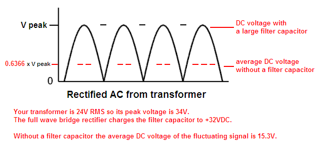
i want to know, does this formular not apply to a bridged network, 0.636(24v - 0.7x4) = 13.48v and the capacitor increases it a little further?
When i tried it first the transformer always burned out until i used a flicker circuit at the battery. it is not included in the diagram as it is not mine.
for the inductor, it is after the rectifier diodes. i think inductors in series affect just dc currents and maintaining the voltage, and in ac the reverse
the LED I bought has the rating of 2-3 volts under specification with current 20-56mA. dO LEDs paralel not have the same voltage with curents shared. (do not get offended. then two finger batteries, 1.5v wont work the normal China torchlight that has up to 20 diodes in parallel?)
and for number 7, if for example an LED of 3.7v is used in series, three in a string, from an 8v source each LED will take its voltage, the barrier potential thing? at the end the drop is 11.8v. so it will be ran on 12v source.
Thanks alot, Audioguru. I look forward to your reply |
|
|
|
audioguru
Nobel Prize Winner
Canada
4218 Posts |
Posted - May 18 2011 : 12:56:30 PM
|
quote:
Originally posted by Sicode
i want to know, does this formula not apply to a bridged network, 0.636(24v - 0.7x4) = 13.48v and the capacitor increases it a little further?
The flucuating rectified voltage is 15.0V which is reduced to 13.5V by the full wave bridge rectifiers.
The filter capacitor smooths the fluctuations which increases the DC voltage a lot. Look at my sketch.
quote:
When i tried it first the transformer always burned out
Because the rectified and filtered voltage was way too high and nothing limited the very high current.
quote:
... until i used a flicker circuit at the battery.
i don't know what is a "flicker circuit".
quote:
the inductor, it is after the rectifier diodes. i think inductors in series affect just dc currents and maintaining the voltage, and in ac the reverse
Inductors were used in power supplies 60 years ago. Yours is simply an expensive resistor.
quote:
The LED I bought has the rating of 2-3 volts under specification with current 20-56mA. dO LEDs paralel not have the same voltage with curents shared.
No, because one might be 2.0V and the other might be 3.0V. then the 2.0V LED will burn out with twice as much current and the 3.0V LED will not light. When the first LED burns out then the second LED will have twice as much current then it will also burn out.
quote:
two finger batteries, 1.5v wont work the normal China torchlight that has up to 20 diodes in parallel?
If a Chinese flashlight is made properly then thousands of LEDs are tested and sorted into groups that have exactly the same voltage. A flashlight with LEDs in parallel uses only one group of matched LEDs. You are not buying thousands of LEDs so you cannot match them then yours will quickly burn out.
A white LED uses 3.3V to 3.6V so two alkaline battery cells making only 3.0V when new will not work. The flashlight uses a voltage stepup circuit that also limits the current.
quote:
if for example an LED of 3.7v is used in series, three in a string, from an 8v source each LED will take its voltage, the barrier potential thing? at the end the drop is 11.8v. so it will be ran on 12v source.
Three 3.7V LEDs in series might be 11.1V or higher or lower because a 3.7V LED might be 3.4V to 4.0V. So the three LEDs might be 10.2V or 12.0V.
So you need a higher supply voltage of maybe 14VDC and a series resistor with enough volts across it or a series current-limiting circuit to limit the current.
Download Attachment:  rectified AC.PNG rectified AC.PNG
26.44 KB
 |
Edited by - audioguru on May 21 2011 7:43:23 PM |
|
|
|
wasssup1990
Nobel Prize Winner
A Land Down Under
2261 Posts |
Posted - May 21 2011 : 12:00:11 PM

|
The RMS voltage of a fully rectified sine-wave with a peak of 1.4V is:
Take a look!
Am I wrong?
|
When one person suffers from a delusion it is called insanity.
When many people suffer from a delusion it is called religion. |
|
|
|
Sicode
Apprentice
67 Posts |
Posted - May 21 2011 : 12:30:53 PM
|
| Wasssup, link breaks. Pls re-post |
|
|
|
wasssup1990
Nobel Prize Winner
A Land Down Under
2261 Posts |
Posted - May 21 2011 : 12:39:12 PM
|
quote:
Originally posted by Sicode
Wasssup, link breaks. Pls re-post
What? |
When one person suffers from a delusion it is called insanity.
When many people suffer from a delusion it is called religion. |
|
|
|
wasssup1990
Nobel Prize Winner
A Land Down Under
2261 Posts |
Posted - May 21 2011 : 10:45:33 PM
|
I see audioguru has updated his image.
My mathematical model has been updated to include calculations for the average voltage of a 1Vpk fully rectified sine-wave. The mathematics there could be useful to look at.
Sorry, I don't have the time to put it in mathematical notation.
|
When one person suffers from a delusion it is called insanity.
When many people suffer from a delusion it is called religion. |
|
|
|
Sicode
Apprentice
67 Posts |
Posted - May 22 2011 : 12:39:11 AM
|
| Great work, wassup and audioguru. |
|
|
|
Sicode
Apprentice
67 Posts |
Posted - Jun 01 2011 : 6:49:57 PM
|
Okay, Audioguru. i just tried this circuit as you illustrated. It works much better,and battery lasts longer. Any more fault in it? The series diodes are now warn;the heat sink is almost cold. wow!
I noticed that the briliance reduced but is however more stable over a given range of time. Thanks |
|
|
|
Sicode
Apprentice
67 Posts |
Posted - Jun 02 2011 : 04:08:53 AM
|
| LM7809 was alot better with the series diode removed. Better brilliance. I forgot to write |
|
|
|
Kenyetta
New Member
1 Posts |
Posted - Apr 17 2012 : 02:10:50 AM
|
How much of voltage is required for a blue led strip?
i hav a blue led strip... i had brought it for my car it was a 5 mtr strip... so i have it on now but i have some left over led strip.. there are 3 led's then one something then more 3 den one something... the strip contains 54 led's.. heres the question: 1.how much of power should i give the strip?...
2..i want to put those on my 60cc bike.. it has a 12v battery on it.. should i connect it directly to the two poles of the battery or should i connect it to the headlight wiring or should i u se a resistor or something?? |
Edited by - Kenyetta on Apr 17 2012 02:11:45 AM |
|
|
|
audioguru
Nobel Prize Winner
Canada
4218 Posts |
Posted - Apr 18 2012 : 9:41:43 PM
|
Kenyetta,
You have hijacked this thread. You should have made your own thread.
Blue LEDs are about 3.5V each. Then three in series use 10.5V. The "something" is a series current-limiting resistor so they can be connected to a car or motorcycle 12V battery.
The LEDs with resistors take only as much current as they need, you do not "give" them current.
Of course you must use a switch to turn them on and off. |
|
|
| |
Topic |
|