| Author |
 Topic Topic  |
|
sparkie
New Member
United Kingdom
2 Posts |
 Posted - Jan 15 2010 : 10:02:36 PM Posted - Jan 15 2010 : 10:02:36 PM


|
Hiya all.
After looking through this thread and the internet and building a few of the circuits I found, I came up with one of my own using a PIC microchip. I havent tried it at a few hundred watts as yet, but I think it will be OK up to about 500w if you have a transformer and battery big enough.
More info on this circuit is here: http://www.m0ukd.com/electronics/modified_sine_wave_inverter/
I would be interested to know if anyone tries it how they get on!
Cheers, John. 

|
 |
|
|
Ibrahim
New Member
Nigeria
2 Posts |
 Posted - Feb 05 2010 : 04:27:03 AM Posted - Feb 05 2010 : 04:27:03 AM


|
| pleas help me i am 17 years old i do electronic work i need 1000 watt inverter circuit diagram that will work faine pleas help me goodby see your messsage thinks |
ibra |
 |
|
|
audioguru
Nobel Prize Winner
    
Canada
4218 Posts |
 Posted - Feb 05 2010 : 10:30:10 AM Posted - Feb 05 2010 : 10:30:10 AM


|
Everybody in Nigeria needs an inverter.
Where are you going to buy a huge and expensive transformer and many Mosfets?
Where are you going to find a huge and heavy battery that runs 1kW for only half an hour? |
 |
|
|
weqwedas
Apprentece

8 Posts |
 Posted - Feb 08 2010 : 7:33:16 PM Posted - Feb 08 2010 : 7:33:16 PM


|
Ibrahim:
A little known fact is that the human body makes a great inverter! All you need is a car battery, a person, and two sets of jumper cables. Hook up the parts like so:

Don't forget the battery polarity! This is important for the organic diodes. Please note that the jumper cable clamps and the voltage surging through the person may be a little uncomfortable at first, but that feeling will go away in a minute or two. If hooked up correctly, the two butt cheeks will begin to alternate contractions. This means that the body has converted the DC into AC successfully! Good luck! |
 |
|
|
wasssup1990
Nobel Prize Winner
    
A Land Down Under
2261 Posts |
 Posted - Feb 08 2010 : 10:55:17 PM Posted - Feb 08 2010 : 10:55:17 PM


|
Be careful some people might actually beleive you and try this. But a good joke anyway.
PLEASE ME NEEDA THE HELP WIT FIVE 1000000000 WHAT INVENTNER! |
When one person suffers from a delusion it is called insanity.
When many people suffer from a delusion it is called religion. |
 |
|
|
weqwedas
Apprentece

8 Posts |
 Posted - Feb 10 2010 : 7:53:16 PM Posted - Feb 10 2010 : 7:53:16 PM


|
| I figured at that point it would be a matter of natural selection. |
 |
|
|
wasssup1990
Nobel Prize Winner
    
A Land Down Under
2261 Posts |
 Posted - Feb 10 2010 : 11:34:16 PM Posted - Feb 10 2010 : 11:34:16 PM


|
| Ha! Yeah. That's a little harsh but that's one way it works. |
When one person suffers from a delusion it is called insanity.
When many people suffer from a delusion it is called religion. |
 |
|
|
Aaron Cake
Administrator
    
Canada
6718 Posts |
 Posted - Feb 13 2010 : 10:49:39 AM Posted - Feb 13 2010 : 10:49:39 AM


|
So after 55 pages, I think it might just be time to close this thread, but leave it as a sticky.
Thoughts? |
 |
|
|
pebe
Nobel Prize Winner
    
United Kingdom
1078 Posts |
 Posted - Feb 13 2010 : 10:55:38 AM Posted - Feb 13 2010 : 10:55:38 AM


|
| I agree. |
 |
|
|
wasssup1990
Nobel Prize Winner
    
A Land Down Under
2261 Posts |
 Posted - Feb 13 2010 : 8:17:53 PM Posted - Feb 13 2010 : 8:17:53 PM


|
Aaron... Do it.  |
When one person suffers from a delusion it is called insanity.
When many people suffer from a delusion it is called religion. |
 |
|
|
weqwedas
Apprentece

8 Posts |
 Posted - Feb 15 2010 : 12:13:09 AM Posted - Feb 15 2010 : 12:13:09 AM


|
| If you can, edit the first post to say that the schematic that links to this thread is very faulty. |
Edited by - weqwedas on Feb 15 2010 12:13:58 AM |
 |
|
|
smeezekitty
New Member
USA
1 Posts |
 Posted - Apr 08 2010 : 9:52:06 PM Posted - Apr 08 2010 : 9:52:06 PM


|
| Is it me or are the caps backwards on the diagram O_o. |
 |
|
|
Cokaric
New Member
4 Posts |
 Posted - Apr 11 2010 : 10:19:08 AM Posted - Apr 11 2010 : 10:19:08 AM


|
Well last time I contacted u was about 4 months ago, in the meantime I examen many circuits but I stick with urs... well PCB is finish now, but I need to ask u few q before I start building it...
#1
Could u check my design ?
#2
Is it possible to modify it for higher power, like 750 W, 850 W or 950 W?
#3
With 500W and 45 Ah battery and consumption of 2,18 Ah in theory it can provide electricity for 20,64 h but I am sure that I would feel effects after only 8h. Is this correct ?
#4
What should be boards copper thickness ?
#5
How wide should lines be, 4 mm ?
Best regards,
Cokaric |
The more I C, the less I see |
Edited by - Cokaric on Apr 11 2010 10:21:08 AM |
 |
|
|
audioguru
Nobel Prize Winner
    
Canada
4218 Posts |
 Posted - Apr 11 2010 : 1:13:49 PM Posted - Apr 11 2010 : 1:13:49 PM


|
quote:
Originally posted by Cokaric
Well last time I contacted u was about 4 months ago, in the meantime I examen many circuits but I stick with urs... well PCB is finish now, but I need to ask u few q before I start building it...
#1 Could u check my design ?
#2 Is it possible to modify it for higher power, like 750 W, 850 W or 950 W?
You forgot to attach your schematic and parts list so we don't know what you are talking about.
quote:
#3 With 500W and 45 Ah battery and consumption of 2,18 Ah in theory it can provide electricity for 20,64 h but I am sure that I would feel effects after only 8h. Is this correct ?[/quote]
A 500W inverter is about 80% efficient so it draws a max of about 625W from the battery which is a current of 52.1A. If the battery current is only 2.18A then the power output is zero since the inverter has an idling current from the battery of more than 2A.
A 45Ah battery supplies 4.5A for 10 hours or 45A for about 15 minutes. It might overheat and boil if it supplies 45A for more than a few minutes. |
Edited by - audioguru on Apr 11 2010 1:20:03 PM |
 |
|
|
Cokaric
New Member
4 Posts |
 Posted - Apr 12 2010 : 06:26:55 AM Posted - Apr 12 2010 : 06:26:55 AM


|
Sorry, I was talking about ur schematic but it seems I didn't express my thoughts well so u were unable to understand me... sorry again...
Ur Desing >>
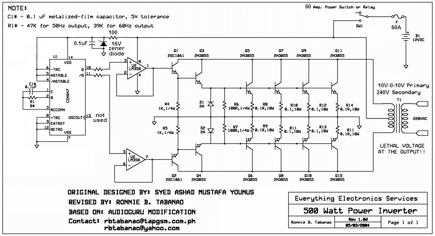
Download Attachment:  20097292438_500W inverter final.PNG 20097292438_500W inverter final.PNG
86.18 KB

PCB >>
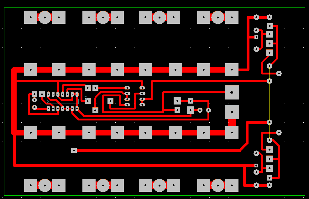
Download PNG PCB:  PCB.PNG PCB.PNG
31.48 KB
Download PCB:  New.zip New.zip
9.56 KB

In PCB I used 0,22Ohm 5W resistors to get 0,11Ohm 10W resistors
In the middle is circle that goes to Emiter of 2N3055 Transistor, his collector is cooler where they are all attached, Base is manually connected with wire from one Transistor to other...
IC CD4047 leg one is down left connected to C1 parallel to R1, leg 4,5,6 & 14 goes to R100 and he is connected to 0 on transformer
ICLM358 leg one is down right connected to base of 2SC1061, legs 6&7 are connected to jumper that goes to base of 2SC1061, leg 8 is connected to 0 on transformer
I order 2SC1061 but they sent me simillar one whos legs are Base, Collector in middle, Emiter...
This is basic, I will draw with my hand elements and re upload picture here...
This has been done in program called PCB Artist
Regards,
Cokaric |
The more I C, the less I see |
 |
|
 Topic Topic  |
|

