| Author |
 Topic Topic  |
|
|
JP04294
New Member
2 Posts |
 Posted - Jul 08 2015 : 9:17:02 PM Posted - Jul 08 2015 : 9:17:02 PM


|
Hello, I was wondering if anyone could help me; I need the (unlisted) value for C18, and also was wondering if anyone could tell me if I would be able to remove the led drivers(to have the all the lights pulse regardless of volume) and instead replace them with potentiometers, WITHOUT having to adjust the resistance values or anything like that for the rest of the circuit?
Here is the link to Aaron's project:
http://www.aaroncake.net/circuits/3chspec.asp
Any and all help would be greatly appreciated, my hope is to put this into my car, so as to provide effect lighting. Hopefully I won't have to mess with the sensitivity of each filter all too much, but that is not my biggest concern at the moment.
ALSO, does it matter if I simply us an audio jack interface instead of a microphone, and also how could I hook up more leds, would I have to adjust the resistor values? |
Edited by - JP04294 on Jul 08 2015 9:19:58 PM |
|
|
audioguru
Nobel Prize Winner
    
Canada
4218 Posts |
 Posted - Jul 11 2015 : 8:49:40 PM Posted - Jul 11 2015 : 8:49:40 PM


|
I do not know where to buy the Japanese LED driver ICs.
The wiring on the schematic for the LED driver ICs is completely wrong. Pin 5 is supposed to be GROUND, not the positive supply. There are other wiring errors so refer to its datasheet.
The LED driver ICs will probably be destroyed by supply voltage spikes if used in a car because the very simple circuit has nothing to stop the spikes.
C18 can be 100uF but in a car it will be destroyed by voltage spikes.
If you remove the LED driver ICs then each one of the the opamp filters might be able to light a single LED when the input is at the correct level. For one LED to light properly regardless of volume then you must add a complicated audio compressor circuit to each frequency channel.
To add more LEDs then of course you must add a powerful LED driver circuit to each frequency channel. |
 |
|
|
JP04294
New Member
2 Posts |
 Posted - Jul 17 2015 : 02:46:22 AM Posted - Jul 17 2015 : 02:46:22 AM


|
quote:
Originally posted by audioguru
I do not know where to buy the Japanese LED driver ICs.
The wiring on the schematic for the LED driver ICs is completely wrong. Pin 5 is supposed to be GROUND, not the positive supply. There are other wiring errors so refer to its datasheet.
The LED driver ICs will probably be destroyed by supply voltage spikes if used in a car because the very simple circuit has nothing to stop the spikes.
C18 can be 100uF but in a car it will be destroyed by voltage spikes.
If you remove the LED driver ICs then each one of the the opamp filters might be able to light a single LED when the input is at the correct level. For one LED to light properly regardless of volume then you must add a complicated audio compressor circuit to each frequency channel.
To add more LEDs then of course you must add a powerful LED driver circuit to each frequency channel.
I apologize for not replying sooner, there have been connection issues at home. Thanks for your input audioguru; on the topic of spikes, would this issue be resolved by tapping into the fuse box rather than directly to the battery and using a 2 fuse tap?
Onto the topic of the drivers, my reason for removing the drivers was not knowing what effect it would have on the way the leds lit up, as most all drivers I have researched light with either a dot or bar style, and I just wish for the whole array(respectively with each filter) to light up consistently. |
 |
|
|
johng
New Member
Canada
2 Posts |
 Posted - Jul 19 2015 : 10:36:29 PM Posted - Jul 19 2015 : 10:36:29 PM


|
Hello,
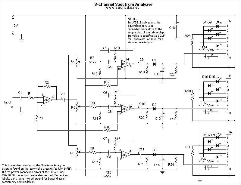
Attached is a revised wiring diagram with corrected power connections.
About AN6884...
- datasheet can be found here:
http://www.bsselektronika.hu/pdf/opto/an6884.pdf
- NTE make a replacement ic for the 6884 (nteinc.com)
- suppliers can be found on eBay (these may be cheap knockoffs,
quality is unknown).
---
@ aaroncake:
Feel free to use the revised diagram
@ JP04294:
1) using the circuit as designed, I think you should be able
to put 3 LEDs in series on each driver output line, assuming
a 12V supply.
I used this idea with an LM3915 circuit, and had 5 LEDs in
series. The circuit was powered by a 12V (nominal) wall wart,
which actually put out about 16V.
2) If you google "voltage spikes in a car" you'll find lots
of info.
3) A microphone signal isn't powerful enough to drive this
circuit (unless it's amplified before feeding to the Analyzer).
As noted in the circuit info, use the "Line Out" of your audio
system. So yes, an audio jack is fine.
Note that the output levels of some devices (mp3 players, etc)
may also not be strong enough. In this case, you could try
boosting U1a gain, and/or adding another stage of amplification.
4) you asked about removing the Driver ICs... technically, yes
that's doable. But you should use something else as a LED driver
(even a simple transistor, to buffer the filter circuit). But
this leads into a whole other project. I don't understand your
idea of using a potentiometer.
5) you say: "wish for the whole array (respectively with each
filter) to light up consistently"
What does this mean?
-----
Edit (July 20/15):
The diagram has been further revised. No errors, just making
the modularity of the sections more obvious.
John
Download Attachment:  3ch spectrum-mod.jpg 3ch spectrum-mod.jpg
95.52 KB
 |
Edited by - johng on Jul 20 2015 3:46:06 PM |
 |
|
|
johng
New Member
Canada
2 Posts |
 Posted - Apr 25 2017 : 09:32:52 AM Posted - Apr 25 2017 : 09:32:52 AM


|
More thoughts/ideas about the Analyzer circuit...
1) for those wanting to use LEDs without the bargraph driver chips, do a search for "Collin Cunningham" on the Makezine website. He has posted a 3-channel circuit which uses transistors as drivers.
2) If you want to use the Analyzer circuit for its entertainment value, then here's something to consider:
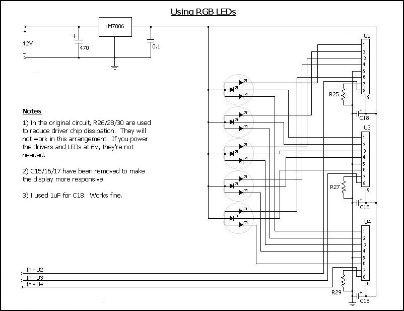
As designed, smoothing is applied to the signal, so the display is slow to release when a peak is reached. This is typical of a VU-type meter display. That's fine for a technical display, but kind of boring entertainment-wise. Reducing/removing the smoothing makes the display much more responsive and interesting. To achieve this, remove C15/16/17 altogether, and reduce the C12/13/14 values (experiment to find what's workable).
3) if you want "spectacular", then consider switching to RGB LEDs. See the attached circuit diagram.
John
Download Attachment:  AN6884 w- RGB LED.jpg AN6884 w- RGB LED.jpg
74.72 KB
 |
 |
|
| |
 Topic Topic  |
|
|
|

