| T O P I C R E V I E W |
| jnewman |
Posted - Nov 23 2010 : 12:45:23 PM
I'm trying to build a 10x10 LED matrix using high brightness LEDs. I understand that these LEDs cannot be powered directly off the microcontroller, so I reckon I need to use transistors to do the job. I came up with the following, but I'm not sure that it's right? I'm not great with transistors, so any help would be appreciated. Also, what specific transistors should I purchase to do the job? I'll be using the microcontroller to go through each pixel on the grid one by one, so the resistor will only need to account for the load of one LED at a time, is this a correct assumption to make?
 |
| 7 L A T E S T R E P L I E S (Newest First) |
| jnewman |
Posted - Dec 01 2010 : 1:43:51 PM
That's great, thanks for your help! :) |
| audioguru |
Posted - Dec 01 2010 : 1:07:57 PM
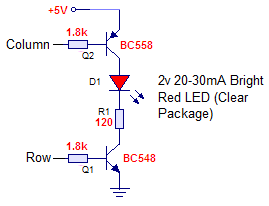
A transistor is a switch when its load is at its collector, not at its emitter.
You are throwing away 10V and making it complicated to drive the PNP transistor since the supply voltage is too high. If the supply voltage for the LED matix is the same as for the micro-controller then it is simple like this:
Download Attachment:  LED matrix.PNG LED matrix.PNG
5.68 KB
 |
| jnewman |
Posted - Dec 01 2010 : 07:08:37 AM
Do you think you could have another shot at attaching the schematic you've drawn up for the problem? Many thanks |
| Aaron Cake |
Posted - Nov 26 2010 : 11:48:29 AM
Did you get an error when you tried an attachment? What was the error....
Test attachment:
Download Attachment: funny-pictures-tacocat.jpg
47.26 KB

Seems to work... |
| audioguru |
Posted - Nov 24 2010 : 9:48:42 PM
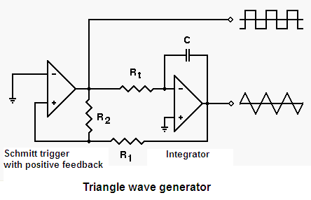
I hate it when people post a schematic on a different website that takes all day to wake up.
Let me see if I can attach a schematic here today:
Download Attachment: Triangle wave gen.PNG
8.86 KB
 |
| jnewman |
Posted - Nov 24 2010 : 12:00:47 PM
I got around the attachment problem by uploading the image to somewhere like ImageShack then using the IMG bbcode tag :)
|
| audioguru |
Posted - Nov 23 2010 : 8:20:52 PM
Your 1k resistor is in the wrong place and limits the LED current to only 2mA which is very dim if it is continuously lighted and is way too dim if it is multiplexed.
The input to the PNP transistor cannot go to ground because its emitter is no lower than 2.1V. Its base current must be limited.
SOMETHING IS WRONG WITH THIS WEBSITE BECAUSE I CAN'T ATTACH A SCHEMATIC. |