| T O P I C R E V I E W |
| foggyeyes |
Posted - Nov 02 2010 : 10:00:52 AM
Your description on how to build a timer relay (http://www.circuit-finder.com/categories/timer/426/time-delay-relay-ii <--- If this is YOU)was very helpful.
I'm working on a project, which requires a circuit to complete after 2.5 minutes ( 150 seconds ).
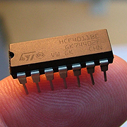
Is this the same IC chip used by You ? http://www.doctronics.co.uk/4011.htm
Also, will the IC require further programming, or is it ready to use ?
Further,
The relay I am planning to use is http://www.popularelectronic.com/asp/product.asp?product=2989
Please advise if it is correct
Thank you.
Download Attachment:  ph4011_01.jpg ph4011_01.jpg
64.12 KB
Download Attachment: LB1.jpg
2.25 KB
 |
| 15 L A T E S T R E P L I E S (Newest First) |
| Aaron Cake |
Posted - Feb 19 2011 : 10:23:41 AM
Cascaded 555s, or a 555 pulsing a counter. Very easy to do.
But as it is assigned by your professor, it is your responsibility to do the work. So look upthe 555 datasheet, and then look up a counter IC (4017). Then figure the rest out. |
| audioguru |
Posted - Feb 18 2011 : 08:28:17 AM
quote:
Originally posted by jeal22
Can i use this http://www.aaroncake.net/circuits/relaytim2.asp?showcomments=all as reference?
As we discussed in this thread, the circuit is too weak to drive a relay. You should use a 555 timer IC instead. |
| jeal22 |
Posted - Feb 18 2011 : 08:02:32 AM
This is the project given to us by our professor:
"It is required to start and run the three 12Vdc motors in sequence using one master START and RESET push button/switch. Once the START button is pressed, motor1 must start to run and followed by motor2 and followed by motor3 with 30 seconds interval from each motor. "
Can i use this http://www.aaroncake.net/circuits/relaytim2.asp?showcomments=all as reference ? and the next problem is that what's next after motor1 started? Can I use the same circuit as given?
|
| foggyeyes |
Posted - Dec 06 2010 : 10:10:38 AM
Yes. Im using a resistor now.
There's a new problem now. The timing works fine using only an LED. Bnut when I use a relay in pararell, The circuit doesnt turn off. Even using JUST a relay, and NO LED doesnt solve the problem/ |
| KMoffett |
Posted - Nov 25 2010 : 11:10:35 AM
Mis-wired and/or a blown 555. Did you place a resistor in series with the LED to limit the current?
Ken |
| foggyeyes |
Posted - Nov 25 2010 : 09:31:39 AM
2 hours is good enough.
I am now using a 555 Timer Circuit (http://www.circuit-finder.com/categories/timer/425/time-delay-relay)
I connected all the components on a breadboard, but when I switch the circuit on, the LED (In place of the relay)turns on without any time delay. Also it stays on even when I switch the circuit off. I even removed the switch and it had no effect on the glowing LED.
Please HELP! |
| audioguru |
Posted - Nov 08 2010 : 4:27:12 PM
The pretty big and old Raytex relay needs 6V at 60mA to drive it so the CD4011 and the CD4069 will not work even if the gates and inverters are connected in parallel. Years ago I used a tiny relay that used 1/12th the current.
The circuit needs an added transistor and resistor to work.
I don't know how long you want the relay to be turned on but a little 9V alkaline battery will power it for only about 2 hours. |
| foggyeyes |
Posted - Nov 08 2010 : 10:44:20 AM
Here is the data sheet for the relay that Im using.
http://www.relay-rayex.com/downloadfiles/LEG_SERIES.pdf
Will this work with the current from the 4011 ?
its a small, new looking one, as suggested by audio guru.
If this WONT work, please, please, please, tell me a relay (from Rayex, t=since they're the only available ones)that will |
| pebe |
Posted - Nov 08 2010 : 09:08:03 AM
Hold the chip with the pins facing away from you and the notch at the top.
Pin1 is then the left hand top pin. Count anticlockwise from there for the others. |
| foggyeyes |
Posted - Nov 08 2010 : 07:50:16 AM
How do you determine which pin is which ?
I placed it such that the writing was facing me, and started from the left.
|
| foggyeyes |
Posted - Nov 07 2010 : 10:01:52 AM
Sorry for being thick.
I see it now. |
| audioguru |
Posted - Nov 07 2010 : 09:59:46 AM
Can't you see that everything connected to the (+) terminal of the battery on the schematic are connected together?
Don't you understand that everything connected to a ground symbol on the schematic including the (-) terminal of the battery are connected together?
Since wire is almost a dead short and the current in this project is very low then it doesn't matter where things connect together. |
| foggyeyes |
Posted - Nov 07 2010 : 12:37:20 AM
Same for the negative terminal. Do i connect C1 and the grounded pins individually to the negative terminal, or should I connect the grounded pins to C1, and the whole thing to the negative terminal ? |
| foggyeyes |
Posted - Nov 07 2010 : 12:30:48 AM
I got the part about the relay. Will do so.
Is the positive terminal connected to the circuit in two places , or just to the 14th pin ? |
| audioguru |
Posted - Nov 06 2010 : 2:18:15 PM
All the grounds are simply connected together and also connect to the negative wire of the battery.
The ground symbol is used on a schematic to prevent ground wires running all over the schematic.
The circuit is not connected to earth.
It is obvious how C1 is connected.
But this circuit will not work unless you find a relay that uses an extremely low coil current or unless you add a transistor to drive the relay. |