| T O P I C R E V I E W |
| ahonda55 |
Posted - Jan 17 2010 : 2:24:44 PM
Hello, i built a Infrared switch circuit, which consists of three ICs, LM339 to amplify the signal from the phototransistor, a NE555 to produce one shot signal and an 4017 IC as a toggle switch.
Thigs goes great, range is about 4 meteres !
But, a small but huge problem, if anyone switched on or off any AC equipment in the room or next room, the 4017 takes a clock signal, i mean it changes it's sitiuation from on to off or from off to on.
I am using a transistor and a relay after the 4017 to be able to toggle a AC device on and off, the relay swith itself will produce a small spark, and causes the same problem, i used the relay to toggle a 12v 21W lamp, and the circuit performance was not stable, when i use a LED instead of the lamp it works good as usual !
i think that the noise affects the LM339 circuit, because when i set the referece voltage far up, it works good but the range become very very short, about 30cm.
I tried installing capacitors everywhere, but nothing :(
I think i need something like a noise filter, or something else??
Many thanks in advance.
Greetings
Ahmed
|
| 8 L A T E S T R E P L I E S (Newest First) |
| audioguru |
Posted - Jan 21 2010 : 4:44:49 PM
If you don't use a modern IR receiver IC then you are in the "dark ages". |
| ahonda55 |
Posted - Jan 21 2010 : 3:44:20 PM
Thanks Guru, I found in the datasheet of the LM567 that "highest center frequency" is 500KHz, does that mean that i have a chance to find a remote control freqyency or it is another mater?
Greetings
Ahmed |
| audioguru |
Posted - Jan 19 2010 : 6:28:51 PM
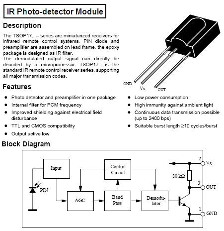
A TV remote control uses a carrier frequency of about 38kHz that is modulated with digital data.
A TV remote blasts current pulses of 1A into its IR LEDs.
The IR receiver in a TV has a filter that reduces visible light, has very high gain and a 38kHz filter.
I don't think an LM567 can follow the data from a TV remote.
Download Attachment:  TSOP IR receiver.PNG TSOP IR receiver.PNG
29.04 KB
 |
| ahonda55 |
Posted - Jan 19 2010 : 4:35:33 PM
Thanks a lot !!
Pepe, i have tried your solutions but still have the same problem, ad yes i have created the circuit on three boards, and all "glued" back to back (to reduce size!!). Inputs and outputs between PCBs are connected via small wires.
Guru, if i used 100k o 10k resistors i can not get it to work, i the TV remote control or sattlite reciever remote control.
GOOD NEWS, the problem have been solved, i have connected a 100uf capacitor between the comparator output and ground, to delay the signal to the 555 a bit, so a light flash or something like that will not affect the circuit, just i have to press the remote control for a second to get the relay switch. A good solution for me.
But, another problem, LIGHT, yes light is my enemy :( when i use the circuit in a bright place i have to set the comparator reference voltage very low to stop the unpredictable switching, thus the range of the remote control decreases badly.
I must use a tone decoder, i built a LM567 tone decoder circuit, but still can not get the TV remote control frequency, very very hard while i dont have the frequency of the remote control.
|
| audioguru |
Posted - Jan 17 2010 : 6:56:27 PM
1M is an extremely high value load for a photo-transistor. Unless the IR level is extremely low use a 10k or 100k resistor. The datasheet for the LM339 says to use a small amount of hysteresis so that the comparator does not oscillate when its inpus are near its threshold voltage.
The reference voltage for the LM339 should have a capacitor filter to ground.
without a schematic I cannot see if the voltage regulator has suitable input and output capacitors. |
| pebe |
Posted - Jan 17 2010 : 4:14:59 PM
It looks like your problem may be modulation of the supply rails, or static pickup on the LM339 inputs. Have you built this on a breadboard with long-ish connecting wires? If so that may be the reason.
In any event I would feed the LM339 +ve supply through a 1k resitor decoupled with 1uF tantalum cap. Let that also feed your two dividing networks. If your IR trigger is not fast then I would also put a 1nF cap between the two inputs of the LM339. I don't like amps working at uncontrolled gain and I would get some feed back into the circuit to cut the gain back a bit. |
| ahonda55 |
Posted - Jan 17 2010 : 3:24:34 PM
Well, i do't have a drawing, but, in a few words, things goes like this..
photo transistor and a 1M ohm resistor consists a voltage devider to feed the inverting input of the LM339
The non inverting input is connected to a 100Kohm pot. which sets the reference voltage, so it is a matter of few millivolts to trigger the output of the comparator.
the output is conncted to the trigger terminal of a 555 monostable timer, and the timer time is set to about 1 second.
the output of the timer is a clock signal to a 4017 decade counter. The decade counter circuit forms a toggle switch, using only two outputs, 1 then 2 then 0 then reset then one ...
the output number 2 is connected to a 2N2222 PNP transistor to drive a 12v relay with the safety diode installed !
All power supply voltages are connected after a voltage regulator.
I thought it will not be that far, but in a low light room it can reach about 5 meters, which is very good for my use.
The circuit is very simple with no complications.
Thanks a lot |
| pebe |
Posted - Jan 17 2010 : 2:57:12 PM
Your information is not much good without a circuit! |
|
|