| T O P I C R E V I E W |
| JUAN DELA CRUZ |
Posted - Aug 09 2008 : 07:28:33 AM
Hi everyone...
A undergraduate student is seeking some 'tips' in calculating parts value in designing a Window comparator.
I've searched in google and found this comparator ckt. with 'HYSTERYSIS':
Download Attachment:  Adding Hysterysis to Comparator.GIF Adding Hysterysis to Comparator.GIF
13�KB
I am trying to design a Window Comparator ckt. as the High/ Low detection ckt... but I was confuse in the above stated formula.
I found in different thread that used 741/ LM10 op-amp as the Low-batt. cut-off ckt...
.. but I will use a Quad op-amp (like LM324/ LM348) instead and
I want to design by my self to learn such basic things. Unfortunately, my know-how is really limited 'coz I am an undergraduate.
So, could anyone tell me the other formula needed (in a comprehensible way) in calculating parts value, voltage ref.,etc. ..but in this case using Zener with pull-ups resistor as the reference voltage and also the formula in calculating 'hysterysis'..
Any help would be greatly appreciated.
Thank you.
|
| 15 L A T E S T R E P L I E S (Newest First) |
| audioguru |
Posted - Sep 05 2008 : 7:30:36 PM
Your battery voltage is from 11.9v to 13.8V when it does not have a load (open circuit). Its voltage is less when it drives a loaded inverter.
Ohm's Law determines the current from the 2N3906.
The CD4047 has a max allowed supply voltage of 18V to 22V. Use a 15V or 16V zener diode instead of a 12V one.
Where is 100mA going to go?
|
| JUAN DELA CRUZ |
Posted - Sep 04 2008 : 01:15:05 AM
quote:
Originally posted by audioguru
Hi Juan,
Texas Instruments show graphs of typical and minimum output currents at various supply voltages for their Cmos gates and inverters. with a 13.5V supply the minimum output current is 6mA when the output voltage drops 3V.
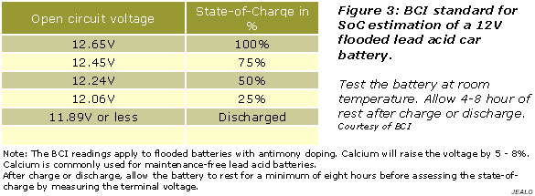
Download Attachment: 12V Flooded Lead Acid Car Battery.PNG
12.04 KB
Audioguru,
Using a 12V Flooded Lead Acid Car Battery or any 12V battery,
which o/p voltage of the battery to be consider in designing a Ckt. ?
...I mean the battery reaches 13.8V- 13.5V when charged but its nominal voltage is 12.65V (according to the table @ Battery university) when the load is not connected?
So, does it mean that in my Ckt. here I must consider the supply voltage as 12V not 13.5V ?
quote:
Originally posted by audioguru
Your 2N3704 transistor has a base current of 0.8mA. Its collector current is 3.2mA.
The 2N3906 transistor has a base current of 3.2mA and a collector current of 16mA.
Download Attachment: 2N3704 NPN_datasheet.PNG
73.34 KB

How come the base current of 2N3906 is 3.2mA which equals also to the collector current of 2N3704 in my Ckt. ?
*I need to increase the o/p current from the 2N3906 to approx. 100mA.
BTW.. Do you think the Zener diode is needed to protect the ICs ( MSW drive Ckt.) from voltage spikes ?
Thank you
|
| audioguru |
Posted - Sep 03 2008 : 12:14:14 PM
Hi Juan,
Texas Instruments show graphs of typical and minimum output currents at various supply voltages for their Cmos gates and inverters. with a 13.5V supply the minimum output current is 6mA when the output voltage drops 3V.
Your 2N3704 transistor has a base current of 0.8mA. Its collector current is 3.2mA.
The 2N3906 transistor has a base current of 3.2mA and a collector current of 16mA. |
| audioguru |
Posted - Sep 02 2008 : 1:56:08 PM
Hi Juan,
Your book about transistors shows a linear transistor as an amplifier. Then it needs a voltage divider and an emitter resistor.
Your circuit is using a transistor as an on-off switch so with plenty of base current it turns on and without base current it turns off.
The base-emitter resistors for your transistors turn them off. |
| audioguru |
Posted - Sep 01 2008 : 7:21:08 PM
Originally posted by pebe
quote:
How do you get Q and Q to go low by gating the 4047 off?
The gate at the the output pins of the CD4047 IC that makes the modified sine-wave will turn the Mosfets off.
I used 3-inputs CD4023 NAND gates to drive the Mosfets. Two inputs make the modified sine-wave and the 3rd inputs turn off the Mosfets when the voltage sensing circuit detects a low battery voltage. |
| audioguru |
Posted - Sep 01 2008 : 7:19:50 PM
Originally posted by pebe
[/quote]How do you get Q and Q to go low by gating the 4047 off?
[/quote]
The gate at the the output pins of the CD4047 IC that makes the modified sine-wave will turn the Mosfets off.
I used 3-inputs CD4023 NAND gates to drive the Mosfets. Two inputs make the modified sine-wave and the 3rd inputs turn off the Mosfets when the voltage sensing circuit detects a low battery voltage. |
| pebe |
Posted - Sep 01 2008 : 11:24:46 AM
quote:
Originally posted by audioguru
I do not recommend disconnecting the supply to the CD4047 oscillator to turn it off. Instead I recommend gating it off. Then the two transistors in your circuit are not needed.
How do you get Q and Q to go low by gating the 4047 off? |
| audioguru |
Posted - Sep 01 2008 : 09:19:03 AM
The base of a transistor uses current to turn on, not voltage.
The 4.7k resistor is throwing away most of the current from the 15k resistor. Change the 4.7k resistor to 47k or 100k.
I do not recommend disconnecting the supply to the CD4047 oscillator to turn it off. Instead I recommend gating it off. Then the two transistors in your circuit are not needed. |
| audioguru |
Posted - Aug 31 2008 : 12:53:37 PM
The pushbutton on my latching circuit turns on the inverter if the battery is charged. It does not turn off the inverter.
If the latch is Reset then pushing the button won't do anything.
An "alternate action" circuit has an output that goes high when its button is pushed then it goes low if the button is pushed again. Its output alternates each time the button is pushed.
Inverting gates can be used instead of inverters.
Download Attachment: Alternate-action.gif
6.69 KB
 |
| JUAN DELA CRUZ |
Posted - Aug 31 2008 : 07:02:04 AM
quote:
Originally posted by audioguru
My circuit uses 3-input NOR gates to drive the Mosfets. This circuit drives the third input high which shuts off the Mosfets.
The opamp comparator SETS the flip-flop to turn off the Mosfets when the battery voltage is low. The flip-flop is manually RESET so that when the battery voltage rises when the inverter is turned off (when the battery voltage is detected low by the comparator) then the Mosfets are not turned on again.
The reset button is pushed to start the inverter when the battery is fully charged.
Good Morning ...
Good evening here in the Philippines
Meaning to say, another flip-flop ( Logic gates ) is essential.
*The Logic gates flip-flop Ckt. manually reset so that when the battery voltage rises when the inverter is turned off (when the battery voltage is detected low by the comparator) then the Mosfets are not turned on again.
The reset button is pushed to start the inverter when the battery is fully charged.
> When the inverter is ON (with Fully charge battery),
what will happen if the pushbutton Sw. is being press again ?
....It will turn-OFF the inverter & vice-versa like a touch Sw. ?
Thank you |
| audioguru |
Posted - Aug 29 2008 : 11:39:12 AM
My circuit uses 3-input NOR gates to drive the Mosfets. This circuit drives the third input high which shuts off the Mosfets.
The opamp comparator SETS the flip-flop to turn off the Mosfets when the battery voltage is low. The flip-flop is manually RESET so that when the battery voltage rises when the inverter is turned off (when the battery voltage is detected low by the comparator) then the Mosfets are not turned on again.
The reset button is pushed to start the inverter when the battery is fully charged. |
| pebe |
Posted - Aug 29 2008 : 04:00:00 AM
quote:
Originally posted by JUAN DELA CRUZ
You mean this Ckt. can't turn-off the 4047 through reset Pin9 ?
I thought it only need to a "High" to turn-off th driver.
Look at the data sheet.quote:
BTW.. What is the function of the second flip-flop in this Ckt. ?
I have no idea. |
| pebe |
Posted - Aug 28 2008 : 07:05:36 AM
quote:
Originally posted by JUAN DELA CRUZ
Do you think IT can turn-off the reset (Pin9_4047) & the third input of a 4025 ? ..'coz I am planning to turn-off them simultaneously to make sure that the FETs are off when the battery voltage is low.
I see that the reset pin of the 4047 takes Q low and Q high. You need to make them both low to cut off the FETs. So wire it so the opamp output provides the 4047 +ve supply. When the opamp o/p goes low the 4047 will shut down.quote:
*Regarding the 555 Ckt.
..which is better in my application CMOs type or Bipolar ?
Either one.quote:
How can I turn off the charger when the battery is fully charge ?
..another detection Ckt. ?
Manually with a switch, or with a timer switch. |
| JUAN DELA CRUZ |
Posted - Aug 28 2008 : 04:21:09 AM
quote:
Originally posted by pebe
In the circuit I gave you, the battery cuts out at 11.5V and won't cut in again until the battery reaches 13.5V. It will never reach that until it is recharged.
So:
1. No, it will not oscillate.
2. You do not need a second flip-flop.
Do you think IT can turn-off the reset (Pin9_4047) & the third input of a 4025 ? ..'coz I am planning to turn-off them simultaneously to make sure that the FETs are off when the battery voltage is low.
*Regarding the 555 Ckt.
..which is better in my application CMOs type or Bipolar ?
quote:
Originally posted by pebe
You need two different controls.
1. A relay that will switch on the inverter when mains is not available. When mains is available the battery will be automatically charged and the inverter switched off.
2. A 2 level detector that (when no mains is available and the inverter is being used) switches off the inverter when battery voltage has dropped to 11V, and switches it on when battery reaches 13V.
How can I turn off the charger when the battery is fully charge ?
..another detection Ckt. ?
Thank you |
| pebe |
Posted - Aug 28 2008 : 04:16:13 AM
quote:
Originally posted by JUAN DELA CRUZ
Could this charger can be modify to have no transformer ?
No.quote:
If not do you know a transformerless battery charger ?
No.
|