| T O P I C R E V I E W |
| Sicode |
Posted - May 25 2011 : 11:33:21 AM
555 Timer - Monostable operation
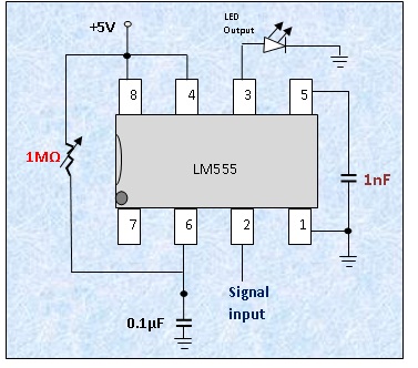
The 555 timer is in a monostable operation with the components as shown in the diagram. The sensitivity of signals to pin 2 if sufficiently noticeable and is seen as light output from pin 3 through the LED (a voltmeter could be used for very small values of voltage). With resistance value very large, output Value at pin 3 is reduced. With the resistance approaching 10 ohms the brightness of the LED is significantly high. Pin two senses electromagnetic field even from a fairly large distance. An EMF of close proximity, say 5m could be sensed – as it all depends on how small the value of the resistance is. The value of the 0.1µF capacitor is another critical factor. Varying the resistance and capacitance offers an interesting changes at the output pin.
Even the EMF from a cell phone could be sensed by the 555 timer. With the resistance close to zero a cell phone ringing about 4m away could be detected – the EMF from the phone is sensed.
The timer also senses body capacitance. This is quite interesting. It can sense a human body over a distance of 20cm.
1. The question now is, what other circuitry could be added to sense signals a great distance away?
2. It seems that the timer sense other signals in the air other than just fields and capacitances. What are these other signals?
3. How could the circuit be modified with other circuits to accurately measure EMF and capacitance?
This is better carried out where there is limited EMF interference from electronic devices, speakers etc.
This is open to all. Every idea is needed.
Thanks in anticipation
Download Attachment:  555 Timer sensitivity.jpg 555 Timer sensitivity.jpg
44.13 KB
 |
| 5 L A T E S T R E P L I E S (Newest First) |
| Sicode |
Posted - May 25 2011 : 1:45:38 PM
ok PEBE. tHANKS. |
| pebe |
Posted - May 25 2011 : 1:34:36 PM
You couldn't use it to measure anything. The transistor input that the pin connects to, is open circuit - a thing no designer would ever suggest - and there is no knowing how the chip would behave.
So like I said, results would be unpredictable and the circuit could not be used, seriously, for anything. Don't waste your time trying to get a logical result from an illogical experiment.
Instead, why don't you study the chip's datasheet and applications so that you can make it do something useful. |
| Sicode |
Posted - May 25 2011 : 12:06:46 PM
I am proud of this Pebe
Thanks alot for a quick reply Pebe. However, what really happens when you come closer to the pin 2. If a finger moves closer to it, or your body, or even a cell phone ringing near it greatly affects the output. It is quite interesting. Apart from this, could the circuit be used for any meaningful thing - based on charges around? |
| pebe |
Posted - May 25 2011 : 11:58:11 AM
Pin 2 of a 555 is its trigger pin. It is sensitive the static voltage present there. It is not influenced by changes of resistance or electromagnetic fields unless they change the voltage on the pin.
The results you are getting are only because the pin is 'floating'. They are purely a fluke and will not be replicable elsewhere unless the exact same set of circumstance are met, ie. humidity, electrostatic charges in the vicinity, and possibly temperature. So you will get no accuracy from it.
If you want to read EMF then use a high impedance buffer before a normal meter, or what's wrong with using a simple digital meter? |
| Sicode |
Posted - May 25 2011 : 11:38:42 AM
Audioguru, Aaron, Wasssup etc, any circuit combination to adequately reproduce a circuit that can accurately read EMF and Capacitance and other unknown signals? I have had this circuit behvae like this for long but now really need to modify it - so that I could use it for something more important and accurate. Thanks!!!!! Up FC Barcelona |
|
|

