| T O P I C R E V I E W |
| fishin_fl |
Posted - May 13 2011 : 08:21:24 AM
I am in the process of building a desk that has a motorized lift raising and lowering my monitors. I manualing do this with a DPDT switch switching polarity to dc 90v motor drive. I am thinking about trying to make this automated. Like upon startup of computer a signal energizes a relay that send the lift up. And then a signal to send it down upon shutdown. Can this be done? I was thinking a micro controller off usb, serial, parrell port, or rs232. THe motor and drive is run off external power supply. Kinda stumpped..... any ideas?! Thanks everyone. |
| 11 L A T E S T R E P L I E S (Newest First) |
| Aaron Cake |
Posted - Jun 01 2011 : 11:05:50 AM
If you have the full version of the datasheet, it will have an example circuit of a one-shot delay timer.
Also, check the 555 timer relay circuits on the circuits page as there are several options. (Time Delay Relay...) |
| fishin_fl |
Posted - May 31 2011 : 12:08:18 PM
I meant to add that I have just downloaded the data sheet on the 555 chip off (www.alldatasheet.com) |
| fishin_fl |
Posted - May 31 2011 : 12:05:38 PM
I was wandering if an off delay 555 timer would work to delay the down operation to this lift. I was reading a lttile on this device. Seems interesting , might be possible. Any ideas on 555 circuit to off delay a 30-180 sec on relay? Thanks everyone that has helped me with my project. |
| fishin_fl |
Posted - May 23 2011 : 10:23:38 PM
Thank you so much I am going try it hopefully tomorrow. This is totally different then what I had setup. |
| pebe |
Posted - May 23 2011 : 2:47:13 PM
quote:
Originally posted by fishin_fl
Thank you for your time. I apreciate your assistance. Do you think using a microswitch would be going over board for I need the lift to do?
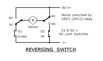
Here is a suitable set-up. A double pole change over relay is used to switch the polarity of the motor. The relay needs to be energised somehow from a signal from your PC. The 90V is always being supplied.
Normally the relay is de-energised, the table is down and the S1 limit switch is open. When the relay is energised the contacts will change over and the motor will run until S2, the top limit switch, is hit and goes OC. The table will stay in the raised position as long as the relay is energised. S1 closed as the table was raised.
When the PC is turned off and the relay de-energises the motor will run and take the table down. When it has reached its low position, S1 will go OC and the motor will stop, ready for next time.
I'm not sure about using micro switches - you will need to check on their specs.
Download Attachment:  Motor reverse.GIF Motor reverse.GIF
3.95 KB
 |
| fishin_fl |
Posted - May 23 2011 : 11:46:46 AM
Thank you for your time. I apreciate your assistance. Do you think using a microswitch would be going over board for I need the lift to do? |
| Aaron Cake |
Posted - May 23 2011 : 10:21:37 AM
I'd have to draw it out when I have some time. |
| fishin_fl |
Posted - May 23 2011 : 09:24:28 AM
Would anyone be able to help me wire this circuit. I have been stumped. I have the two limit switches and just need to now what type of relay and how to wire them. Any help would be great. Thanks |
| fishin_fl |
Posted - May 17 2011 : 12:52:58 PM
I guess now I have the theory but the logic is somewhere else. I have two limit switches one at bottom and one at top. Motor is externally powered 90vcd. Now I have confused my self on relay setup? Ha. Should i be using (2) DPDT relays? Also, how might I wire it. mine does not seem to work. Connections must be wrong. Thanks |
| fishin_fl |
Posted - May 16 2011 : 12:23:18 PM
Thank you so much. I had someone else tell me something like this, but he also recommend what they call a motor bee. Seemed a little over what I need. So it sounds to me that I need two relays. One for the up motion and the down motion, due to polarity switching of dc motor. Thanks you. |
| Aaron Cake |
Posted - May 14 2011 : 10:55:46 AM
It can be easily done. It doesn't even have to be complicated. Just use the power LED signal of the computer to switch a relay, which starts the motors operating. Once they reach their position, a limit switch is activated which stops them and then activates another relay so that when the power LED goes off, the NC contacts of that relay activate the motors again. |

