| T O P I C R E V I E W |
| bosoko |
Posted - Jan 13 2013 : 09:16:27 AM
Hello! I'm building a LED lamp from a bunch of high powered LED's which would eat up about 70V and 300mA when placed in series.
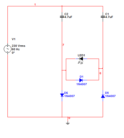
I don't want to play around with transformers and driver circuits so I sketched the circuit below. It works in simulations, but I haven't tried building it yet, mainly because those caps are more expensive than electrolyte ones and because I need a case for it.
Here's the circuit, I hope to receive some criticism before I start building it and it catches fire.

I used caps with the idea that they don't heat up as much as resistors and hence don't waste power (I'd need equivalent 60W resistors in there) and the D1 diode is there as a precaution against wrong-way voltage on the LED's (may be redundant). |
| 6 L A T E S T R E P L I E S (Newest First) |
| audioguru |
Posted - Mar 10 2013 : 4:14:11 PM
Bosoko,
Your new schematic shows a "normal" way to light a few LEDs from the mains without a power transformer.
But the capacitor values are very low so the current in the LEDs will be very low. |
| bosoko |
Posted - Feb 13 2013 : 6:10:02 PM
Hello!
Here's a video of the simulation if the Java one doesn't work: http://youtu.be/IGUZXFslZzo
I tried asking about this on another forum, but they closed my thread because they didn't like the idea of powering LED's by wall sockets :(. So far the only thing I'm worried about is one or more LED's failing and becoming conductive, making other LED's fail because of the capacitors getting more voltage and hence passing through more current. But then again the LED's are rated at 500+mA and I'm planning to drive them with ~350mA, so one or two broken LED's shouldn't do much damage. Also, a fuse should lower the chances of that happening.
There's also a current peak jump on power on which might damage the leds. Another thing is heat management, I'm yet to think of a way to direct heat away from the LED's.
EDIT: there's a better way to do it apparently. audioguru, is this what you had in mind?
Download Attachment:  ledlight_for_50V_50Hz.png ledlight_for_50V_50Hz.png
4.69 KB
 |
| audioguru |
Posted - Feb 13 2013 : 4:52:29 PM
I couldn't make the Java simulation work and I didn't know which of the many programs for it to download.
I see that your circuit uses the two capacitors and the two rectifier diodes to form full-wave rectification so the LED lights on both halfs of the waveform. |
| bosoko |
Posted - Feb 10 2013 : 10:03:59 AM
Aaroncake, I specifically chose the caps because they don't produce waste heat, ideally they store energy and then release it - hence no waste heat. Of course real ones aren't ideal, but they are still much more efficient in that sense than equivalent resistors.
audioguru, could you clarify which parts are extra? I can't think of any except the D1. Also, where should I insert the rectifier and why would I need one if my circuit already uses both halves of the wave? Here's the principle of circuit's operation: link |
| audioguru |
Posted - Feb 04 2013 : 11:59:36 AM
The capacitor will not heat with the very low frequency of 60Hz and the very low current.
Why did you use so many extra parts that would prevent the LED from lighting?
I sketched a very simple half-wave circuit that will cause the LED to blink on and off very quickly.
using a full-wave bridge rectifier instead of the diode will cause the LED to appear lighted solid without blinking.
Download Attachment:  230VAC LED.png 230VAC LED.png
5.16 KB
 |
| Aaron Cake |
Posted - Feb 03 2013 : 11:33:32 AM
Driver circuits are used because they are efficient. You're going to be dissipating all that heat away in those capacitors, or if you choose resistors, you'll be burning it all up there. PWM is the way to go. |

