| T O P I C R E V I E W |
| kivdenn |
Posted - Sep 09 2010 : 10:41:10 AM
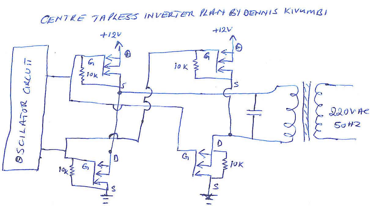
High all i was thinking of reducing on the amount of the long and thick center tapped copper coil primary winding of the power transformer that we use in all our DC-AC inverter circuits and I came up with an idea of having two pairs of mosfet transistors. Once the oscillator turns on one pair, one mosfet draws power from the battery positive terminal and feeds it to one end of the transformer primary winding which is wound for 12V and the other draws the same power from the same winding and shorts it to the ground. The same procedure will happen to the other pair as the oscillator alternately switches them on and off. Have a look at my circuit drawing can it work? Thanks
Download Attachment:  Centre tapless inverter transformer.jpg Centre tapless inverter transformer.jpg
70.69 KB
 |
| 9 L A T E S T R E P L I E S (Newest First) |
| kivdenn |
Posted - Sep 20 2010 : 3:29:47 PM
I will try |
| pebe |
Posted - Sep 13 2010 : 3:42:27 PM
Have you any means of sending money to PayPal? If so, they can pay for the bits for you. |
| kivdenn |
Posted - Sep 13 2010 : 07:59:05 AM
No we cant because we dont have credit card systems here. |
| pebe |
Posted - Sep 11 2010 : 2:58:15 PM
quote:
Originally posted by kivdenn
I had already seen that circuit but the problem is that I cant get P Chanel fets from my country. All you can get are the N channel fets and the other thing is that this circuit gives limited out put, I hear it cant go beyond 500 watts. What is the exact problem with my circuit? Thanks
Dennis
Uganda
Can't you buy from Ebay in your country? You can find people selling everything you want there. |
| audioguru |
Posted - Sep 11 2010 : 2:15:17 PM
I can't remember the part number of a Mosfet Driver IC because I have never used one. If I want a P-channel Mosfet then I simply buy one, then a Mosfet driver IC is not needed.
Google says that a MAX622, MAX1614 or IR2110 is what you need but you must learn how to use them yourself.
I doubt you can find them in your country. |
| kivdenn |
Posted - Sep 11 2010 : 01:40:48 AM
Could you please modify my circuit with that mosfet driver IC included. Thanks |
| audioguru |
Posted - Sep 10 2010 : 6:24:20 PM
The problem with your circuit is that the Mosfets that pull up need a gate voltage that is 10V higher than their source voltage. You want the source voltage to be close to +12V when the Mosfet is turned on then the gate voltage must be +22V.
How will your oscillator produce pulses at +22V?
EDIT: There are Mosfet driver ICs that use bootstrapping to drive the gates of upper N-channel Mosfets with pulses that are 10V higher than their source voltage. |
| kivdenn |
Posted - Sep 10 2010 : 04:59:41 AM
I had already seen that circuit but the problem is that I cant get P Chanel fets from my country. All you can get are the N channel fets and the other thing is that this circuit gives limited out put, I hear it cant go beyond 500 watts. What is the exact problem with my circuit? Thanks
Dennis
Uganda |
| JUAN DELA CRUZ |
Posted - Sep 10 2010 : 04:38:47 AM
hi kivdenn,
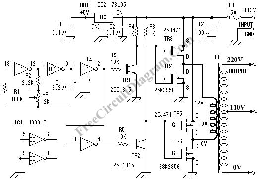
I think your ckt. won't work with regards to the configuration of your Mosfets. I found a simple Low frequency type inverter using center-tapless transformer. ( I dont if it is working )
But, one thing is for sure the total voltage drop across the FETs using this config. increased. And the effeciency decreased compared with the simple low freq. inverter using center-tapped.
Download Attachment:  Inverter without centertapped.gif Inverter without centertapped.gif
14.06 KB
 |

