| T O P I C R E V I E W |
| sailmike |
Posted - Jun 26 2011 : 06:00:26 AM
Hi, I'm trying to modify a LED chaser circuit so that it has 20 outputs, but with only ONE output on at a time. This would mean adding a second 4017B chip. Sure I could set it up so that it counts from 0-99, but this would cause two outputs to be on at the same time at all times. This is not what I want. Does anybody know how to do this?
Thanks,
Mike |
| 15 L A T E S T R E P L I E S (Newest First) |
| wasssup1990 |
Posted - Jul 03 2011 : 11:18:56 PM
An example:
Load: 200mA (I) constant current
Battery: 300mAh capacity rated at a constant current draw of 200mA
How long will the battery last (until regarded fully discharged by the manufacturer)?
capacity / I = 1.5 hours = 90 minutes with a 200mA constant current load
A battery's capacity rating (usually measured in Ah) varies depending on the load.
There's more to it than that, so go here to learn more:
http://www.youtube.com/watch?v=R8hTQXqURB4 |
| audioguru |
Posted - Jul 03 2011 : 8:50:51 PM
You must look on the website of a battery manufacturer and see the spec's for the selected battery.
A battery voltage drops as it is used and your LEDs will get dimmer and dimmer until they cannot be seen. You must calculate or test for the lowest acceptable battery voltage then look at the voltage of the battery on its datasheet after a discharge.
Example: An Energizer 9V alkaline battery has a spec'd capacity (mAh) when its voltage has dropped to only 4.8V. The mAh numbers are much less when the voltage drop is less;
625mAh when the load is only 25mA.
380mAh when the load is 300mA.
300mAh when the load is 500mA.
So a 9V alkaline battery might power 144mA worth of LEDs for about 1 hour when they will have dimmed to be useless.
|
| sailmike |
Posted - Jul 03 2011 : 2:23:29 PM
Alright, say I have a string of LED's that uses 144mA and I have a battery pack of 300mAH. If that's 144mA/s, then the pack will go dead in about two seconds?
Thanks for your help,
Mike |
| wasssup1990 |
Posted - Jul 03 2011 : 12:52:04 AM
quote:
Originally posted by sailmike
Sorry, I was talking about the LED's, not the batteries. When manufacturers say a LED uses 25mA, does that mean per hour?
Thanks,
Mike
Amperes is a rate measurement of Coulombs.
I = Q/t
In words, "Amps" measure how much charge (measured in Coulombs) passes through an area, per second.
If your manufacture says the LED "uses" 25mA, then that means 25mC (Coulombs) will be flowing through your LED per second.
"25mA per hour" doesn't make any sense in this context unless you are talking about the rate at which current changes. This is all basic electronics. |
| sailmike |
Posted - Jul 02 2011 : 8:49:16 PM
Sorry, I was talking about the LED's, not the batteries. When manufacturers say a LED uses 25mA, does that mean per hour?
Thanks,
Mike |
| audioguru |
Posted - Jul 02 2011 : 8:29:50 PM
Energizer has a website with datasheets for every battery they make. They show the time a battery goes dead at different currents. |
| sailmike |
Posted - Jul 01 2011 : 05:52:27 AM
Great! Thanks for your help! This circuit is for lighting up more than 300 LED's that are going into my 40" saucer rocket. I want 20 outputs so that I can spread out the load and never use more than 144mA. I do have one last question: when manufacturers list the amp draw, like 25mA, is that the amount that's consumed in one hour? I need to know so that I can figure out what size battery pack to use.
Thanks again,
Mike |
| audioguru |
Posted - Jun 29 2011 : 5:03:47 PM
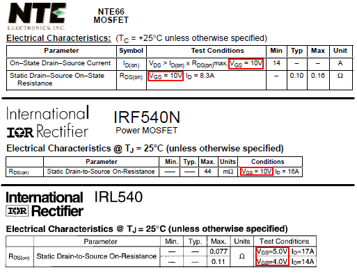
The datasheet for every Mosfet lists its ON-RESISTANCE when its gate-source has a certain voltage that is usually 10V. "Logic level" Mosfets like the IRL540 have their ON-RESISTANCE spec'd when the gate-source voltage is fairly low.
Download Attachment:  Mosfets datasheets.PNG Mosfets datasheets.PNG
40.67 KB
 |
| sailmike |
Posted - Jun 28 2011 : 8:25:42 PM
How did you come up with the figure of 10V to turn it on completely? I do have some knowledge on how transistors work.
Thanks,
Mike |
| audioguru |
Posted - Jun 28 2011 : 1:05:53 PM
quote:
Originally posted by sailmike
Ah I didn't know that about the NTE 66. Do you know where I can get it cheaper?
You didn't hear me.
NTE do not manufacture anything. They buy transistors, erase their part numbers and print their own part numbers. Then they raise the price a lot.
The NTE66 is 100V and 14A. It costs $7.64 each at Newark but today they are on sale for $6.12 each.
The IRF540 Mosfet is made by many semiconductor manufacturers and is 100V and 28A so it is twice as good as an NTE66. It costs $1.43 each at Newark today.
quote:
Where do I find the minimum voltage requirement for the NTE 66 on the data sheet? Is this the "gate threshold voltage"? My data sheet says between 2 and 4 volts for this.
Minimum voltage to do what?
The NTE66 and IRF540 turn on completely when their gate-source voltage is 10V or more (a max of 20V).
The threshold voltage of 2V to 4V is when they are barely turned on (or almost turned off) with a minimum current of only 0.25mA. |
| sailmike |
Posted - Jun 28 2011 : 01:51:00 AM
Ah I didn't know that about the NTE 66. Do you know where I can get it cheaper?
The supply voltage will be via two lithium poly packs giving 16.8 volts max. I've used the 4017B to drive the mosfets without any resistors in series and it works fine, so I'm assuming it'll work here. The data sheet for both chips from ST shows an output of about 15 volts when the supply voltage is 15+ volts.
Where do I find the minimum voltage requirement for the NTE 66 on the data sheet? Is this the "gate threshold voltage"? My data sheet says between 2 and 4 volts for this.
Thanks for your help,
Mike |
| audioguru |
Posted - Jun 27 2011 : 11:03:32 PM
The 4047 oscillator divider driving the 4017 might work.
NTE don't make transistors. They buy them from transistor manufacturers, mark them with their own part numbers and resell them at a much higher price as "replacements".
The NTE66 is not a bipolar transistor that your schematic shows. It is a Mosfet. It needs 10V on its gate to turn on completely. A 9V battery drops to only 6V during its life so the Mosfet should be a logic-level one that works well with a gate voltage of only 5V to 6V.
A Mosfet has a high gate capacitance so it needs a low value resistor (10 ohms to 100 ohms) in series with its gate to prevent oscillation. |
| sailmike |
Posted - Jun 27 2011 : 03:30:43 AM
The circuit I'm talking about is:
http://www.diybanter.com/attachments/electronic-schematics/4201d1225536619-20-led-chaser-seb-20-led-chaser-pdf-led-chaser-pdf
Can I replace all of the transistors with the NTE 66 transistor? Also, are the 3.3k resistors necessary? I don't use any resistors for my 10 LED chaser.
Thanks,
Mike |
| sailmike |
Posted - Jun 27 2011 : 03:21:09 AM
To me it looks like one of the diodes that make up the "AND" gates is backwards, because the output from pin 3 of the 555 timer can't go through. Or did I read it wrong?
I found another circuit that uses a 4047 and 4017 to get the 20 outputs. I've built a chaser circuit with an NTE 66 transistor at each of the outputs so that I could run as many LED's as I like at each of the outputs and with full current for maximum brightness. Because the NTE 66 transistor is rather expensive, the circuit using the 4047 and 4017 would use only two more NTE 66 transistors and save me money.
Thanks,
Mike |
| audioguru |
Posted - Jun 26 2011 : 11:49:57 AM
I think I may have found my answer at the following link:
http://focus.ti.com/lit/ds/symlink/cd4017b.pdf
On the page labeled 3-55 figure 19 shows how to cascade the 4017. Is this the answer I'm looking for? Also, what does CE stand for?
[/quote]
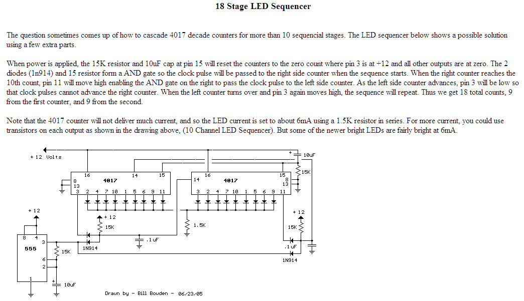
It shows that two CD4017 ICs make only 17 outputs so for 20 outputs you will need three CD4017 ICs.
On Bill Bowden's site he makes the AND gates with diodes and a resistor. His circuit has 18 outputs with two CD4017 ICs.
CE is Clock Enable NOT which is actually Clock Inhibit pin 14.
Download Attachment: cascaded 4017s-2.PNG
45.19 KB
 |