| Home > RX-7 > Tech/Mods > Modifications > Turbo NA Guide > Turbo Oil/Water Lines, Intake Adapter, Boost Gauge |
| Home > RX-7 > Tech/Mods > Modifications > Turbo NA Guide > Turbo Oil/Water Lines, Intake Adapter, Boost Gauge |
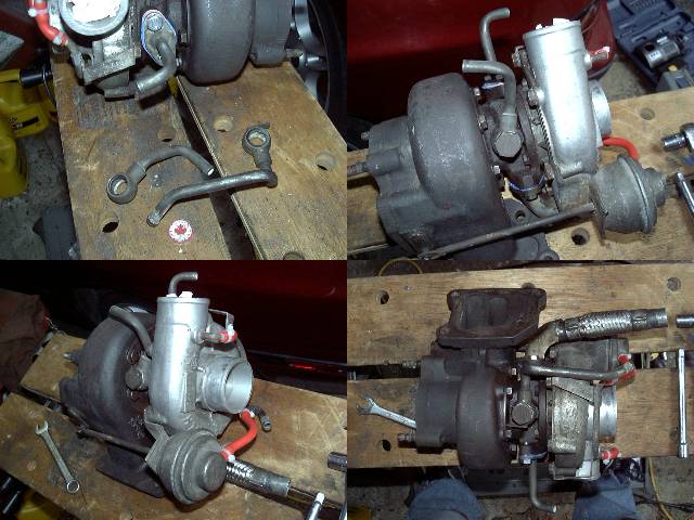
The wastegate was reinstalled onto the turbo, and then oil and water lines were made up out of stock TII lines. Mostly, things were just trimmed. As it shows in the picture, a water feed line was cut in half to make oil feed and water feed fittings. The stock water drain was used as is, and the stock flange was cut off the oil drain line. All new gaskets were used, along with the traditional blue gasket goo to help seal things up.
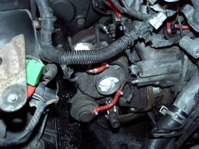
It was time to permanently bolt the turbo to the manifold. With the new notch in the frame, everything fit fine. The only problem was tightening the last (upper front) bolt. Space was so limited that a wrench had to be cut down to a quarter of it's size, and then a hammer and drift used to tighten the bolt. It was not fun.
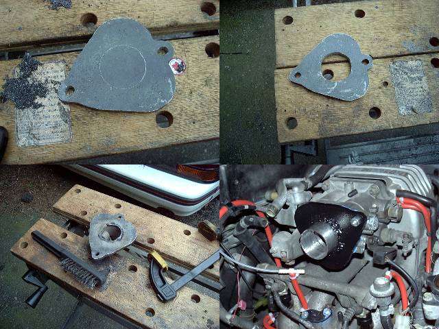
A way to connect the intercooler piping to the upper intake/throttle body was required, so a custom air horn was created. This air horn became known as "The Strawberry" for obvious reasons. It is made out of 5MM thick steel, with a section of stainless steel 2" pipe welded on. Because of the sudden transition between the 2" pipe and the wide throttle body, there is quite a bit of turbulence produced. The Strawberry will be eventually replaced with a more smoothly contoured piece. Also shown in the last picture is the vacuum line and T for the boost gauge/BOV.
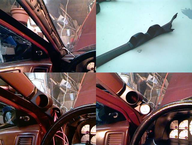
For a change of scenery, I went inside the car to install the boost gauge. As you can see from the previous picture of The Strawberry, a plastic T was connected to the upper intake via an unused factory vacuum nipple. The capillary tubing for the gauge runs along the firewall, to a hole drilled near the brake booster. It then runs under the dash up to the A pillar. To mount the gauge, a standard AutoMeter gauge pod was used. Since there are two pods, an EGT gauge will eventually be installed in the second opening. Wires to power the backlight on the boost gauge were run down the A pillar to a body ground and the illumination terminal on the headlight switch. This allows the boost gauge to be dimmed like the factory installed gauges. Extra wire was also run for the 2nd gauge.