| Author |
 Topic Topic  |
|
audioguru
Nobel Prize Winner

Canada
4218 Posts |
 Posted - Oct 12 2008 : 3:08:18 PM Posted - Oct 12 2008 : 3:08:18 PM


|
quote:
Originally posted by yunusu
It's possible to adjast the output fo an inverter
by using a simple variable resustor in it's
oscilator ? how
Adjust what? A variable resistor can adjust the frequency. |
 |
|
|
forlan12
New Member
4 Posts |
Posted - Oct 13 2008 : 03:45:41 AM
|
can u guys help me.
in my project, i have to replace the inverter IC into PIC microcontroller.
1)i want to find the replacement component for 2sj471- pnp mosfet.
2)what specification should i look in the datasheet?
3)is it irf9450 suitable for replace 2sj471?
|
|
|
|
audioguru
Nobel Prize Winner
Canada
4218 Posts |
Posted - Oct 13 2008 : 12:06:51 PM
|
You found a low power Japanese inverter circuit. Of course it uses Japanese parts.
Its output is a simple square-wave that will not drive many electronic products properly.
It uses 4 Mosfets because it doesn't use a center-tapped transformer when it needs only 2 N-channel Mosfets.
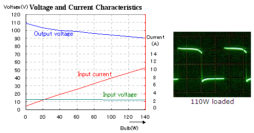
Its performance is horrible because it does not have voltage regulation. With no load then its output voltage is 10% high. With a 40W load then the output voltage is correct. With a 140W load then the output voltage is 10% low.
If you use a center-tapped transformer then the output power would be double with only 2 of those Mosfets.
http://hobby_elec.piclist.com/e_ckt30.htm
what will a PIC do? If it produces a high frequency PWM signal to make a stepped sine-wave then the transformer must be different and the transistors must switch quicker.
Download Attachment:  110W inverter.PNG 110W inverter.PNG
50.02 KB
 |
Edited by - audioguru on Oct 13 2008 12:07:58 PM |
|
|
|
forlan12
New Member
4 Posts |
Posted - Oct 13 2008 : 2:44:23 PM
|
quote:
If you use a center-tapped transformer then the output power would be double with only 2 of those Mosfets.
what will a PIC do? If it produces a high frequency PWM signal to make a stepped sine-wave then the transformer must be different and the transistors must switch quicker.
PIC produce PWM signal. i plan to make sine-wave inverter 12/240V.
plz corect me if i wrong.
the transformer should be 12V-0V-12V and its center-tap connects to the positive supply. The sources of the N-channel Mosfets (2sk2956)connect to ground.
btw what mosfet should i use? is it IRF9540 suitable for replacement 2sj471?
Download Attachment: power invert edit.GIF
9.5 KB |
|
|
|
audioguru
Nobel Prize Winner
Canada
4218 Posts |
Posted - Oct 13 2008 : 6:40:28 PM
|
The IRF9540 is a weak low power P-channel Mosfet. It is not needed with the center-tapped transformer.
Your new circuit shows a low frequency square-wave inverter, not a high frequency PWM sine-wave one.
The peak voltage of a square-wave is the same as its RMS voltage. But the peak voltage of a sine-wave is 1.414 times higher so the transformer must be about 9V-0V-9V to make the higher peak voltage for a sine-wave. The PWM transformer must be a small high frequency ferrite one. |
|
|
|
forlan12
New Member
4 Posts |
Posted - Oct 14 2008 : 12:30:15 AM
|
is it ok, if i change the circuit by changing the placement of mosfet into full-bridge.
all the mosfet are 2sk2956 npn.
any recommend , what mosfet should i use other than 2sk2965?
i prefer mosfet IRF brand
Download Attachment: power invert2.GIF
10.35 KB |
|
|
|
audioguru
Nobel Prize Winner
Canada
4218 Posts |
Posted - Oct 14 2008 : 10:58:30 AM
|
quote:
Originally posted by forlan12
is it ok, if i change the circuit by changing the placement of mosfet into full-bridge.
It won't work because the upper N-channel Mosfets need a gate voltage that is 10V higher than the source voltage. Then the gate voltage must be +22V to +24V.
Usually a full-bridge Mosfet driver IC is used that has a voltage doubler circuit inside for driving the upper (high side) Mosfets.
The Mosfets are selected for the amount of output power you want from the inverter. |
|
|
|
mleiss
New Member
2 Posts |
Posted - Oct 18 2008 : 01:02:18 AM
|
| This is in regards to simply multivibrators like the original schematics shown. With switchers and inverters it is wise to know if there is a "dead band" between the switching pulses, especially if there is more than one transistor in the switching circuit. When one transistor switches off, the other one is turning on and there is a moment in time where both are on, though very brief. This has a detrimental effect on your efficiency of the circuit. Also, since both transistors are on for that brief moment, guess what this does to the current... All of the current in the circuit goes to ground, essentially removing the stored energy that is in the system and effecting efficiency because now your supply has to provide additional energy to make up for the losses. So to make this work, and I haven't tried this circuit out myself either, I believe that a more sophisticated clocking source would be required to allow about 200ns to 400ns of a dead zone between each triggering pulse of the transistors. |
|
|
|
gim
Apprentece

5 Posts |
Posted - Nov 07 2008 : 04:27:12 AM
|
Audioguru, if I may ask you a question.
I have built an inverter, which works, as I have mentioned before. I have added to it a light sensitive switch, so that it turns on in daylight, and turns off in darkness. The switch consists of an LDR connected to a 555 timer IC, which does the switching, and in turn drives a MTP3055E MOSFET through a 47 ohm resistor.
The trouble is, sometimes, the circuit (I guess that is the MOSFET) oscillates at radio frequencies. It makes quite loud intereference on the audio of my TV.
Can you suggest a way to stop this HF oscillation? Would increasing the gate resistor of the MOSFET do it, and if so, what value should I use? |
|
|
|
audioguru
Nobel Prize Winner
Canada
4218 Posts |
Posted - Nov 07 2008 : 12:25:30 PM
|
| A resistor in series with the gate of a Mosfet stops it from oscillating at VHF frequencies. It should be mounted directly at the gate pin, not connected by a wire. 4.7 ohms to 100 ohms should work fine. |
|
|
|
mleiss
New Member
2 Posts |
Posted - Nov 11 2008 : 9:57:17 PM
|
If this doesn't work for you, try a RC snubber network between the drain to source of your MOSFET. You may have incurred a resonance or ringing between the leakage inductance of the transformer and the output capacitance of the MOSFET. Adding the RC snubber will help to reduce the ringing.
First, figure out what the frequency of the oscillation is, if you have a way. You can use this frequency to calculate the leakage inductance of your transformer with the following equation: L = 1/((2*pi*frequency)^2*Capacitance).
Select a capacitor that is about 3 to 4 times larger than the output capacitance of your chosen MOSFET. This should reduce the frequency of the resonance by a factor of 2. Then calculate your resistance based on the equation for characteristic impedance of a parallel resonant circuit as in the following equation: R = sqrt(L/C).
After the R-C circuit has been calculated, again place the resistor and capacitor in series between the drain and source of your MOSFET. Ensure you have a very good ground and minimize the lead length between the capacitor and ground. If the connections between all of these elements are not short, parasitic elements of a long wire can change this circuit and you will not dampen out the oscillations as you thought you would.
Hope this helps and good luck! |
|
|
|
fallo
New Member
1 Posts |
Posted - Nov 19 2008 : 12:52:37 PM
|
Hi, I�m currently working in building a photovoltaic system to power a complete room and at the end a complete house, do you have any idea of how much power would it need to generate. I�m asking this cause obviously I need an inverter DC-AC, and I want to try building it my own, or would it be better if I buy it custom made? I appreciate your suggestions, thanks.
Fallo |
|
|
|
audioguru
Nobel Prize Winner
Canada
4218 Posts |
Posted - Nov 19 2008 : 2:25:53 PM
|
Simply add the amount of power you need for everything in the room. Then figure that not everything will be turned on at the same time. The result is the amount of power the inverter must supply.
Good inverters work well and are inexpensive. Solar panels are expensive. Windmills are less expensive. |
|
|
|
paul_ma7
New Member
3 Posts |
Posted - Nov 22 2008 : 11:17:32 PM
|
i build the inverter but for some reason the current
is very low it will only handle about 2 amperes,
i'm thinking it might have something with the battery?
my batt is 12.7v and 7 amp, do i need to use a car battery?
also i'm not using the hep diodes, i'm using a regular silicon diode, |
|
|
|
paul_ma7
New Member
3 Posts |
Posted - Nov 22 2008 : 11:29:30 PM
|
| also i forgot to mention that i'm using a 150w transformer not the 300w transformer |
|
|
|
Topic |
|
 power invert edit.GIF
 power invert2.GIF