| Home > RX-7 > My RX-7 > Project Tina > Project Tina, August 7th, 2006: Fuel System, Intake Manifold Installation, Exhaust Fabrication |
| Home > RX-7 > My RX-7 > Project Tina > Project Tina, August 7th, 2006: Fuel System, Intake Manifold Installation, Exhaust Fabrication |
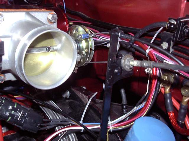
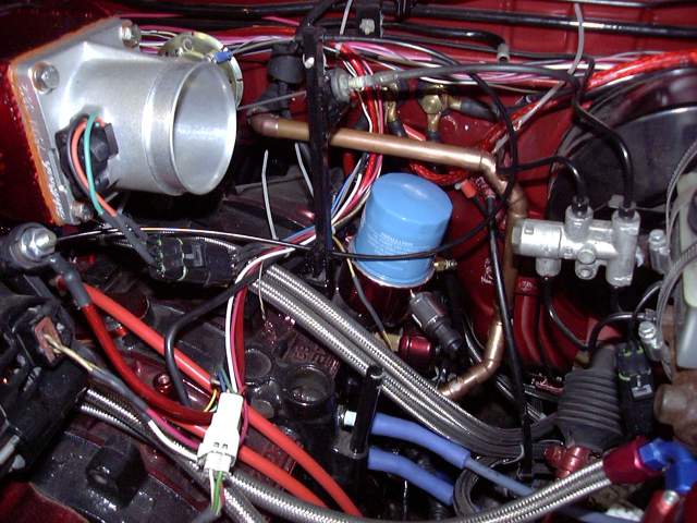
That pipe took about half an hour to cool to the point where I could pick it up, so in the mean time I installed the throttle cable bracket. The bracket was made using the stock throttle cable bracket from the original throttle body, a small square of 12 gauge sheet metal and then a piece of angle iron. The sheet metal base bolts to the two holes in the top of the rotor housing that used to hold the vacuum spider and the angle iron is mounted vertically to it. The OEM throttle bracket was then welded to the angle iron.
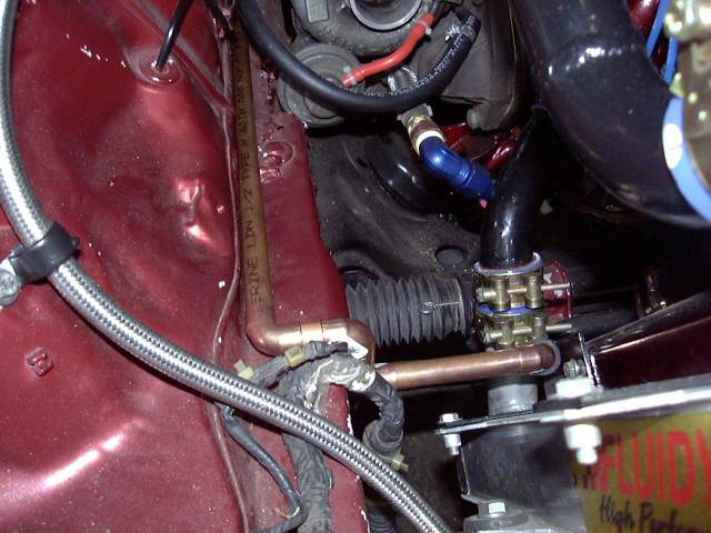
The top cable is the aforementioned metering oil cable. It's a simple arrangement of bicycle brake cable held in place with a small cable clamp. A bolt extends through an extra hole in the throttle spool and the cable attaches to that with a standard crimp-on eyelet. A nylock nut prevents the eyelet from slipping off.
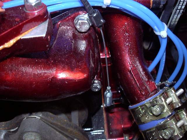
On the metering oil pump end, another cable clamp secures the cable to the lower intake mounting bolt. A spring connects to the metering oil pump lever and another eyelet connects the cable to the spring. The spring is necessary as the metering oil pump is adjusted fairly loose, about twice that of stock. So it reaches wide open before the throttle plate does. The spring takes up the slack. OK, so it's a little Rube Goldburg, but no more then the stock setup with rods and shims.
Now that the downpipe had cooled, the rest of it could be made. Because it's all temporary, I just used cheap aluminized steel 2.5" exhaust tubing. It was assembled to the proper length, and then welded to the downpipe.
The finished downpipe also has an oxygen sensor bung just visible on the bottom of the pipe after the turbo flange.
All told there is about 2 hours invested in this pipe from start to completion, and under $100.
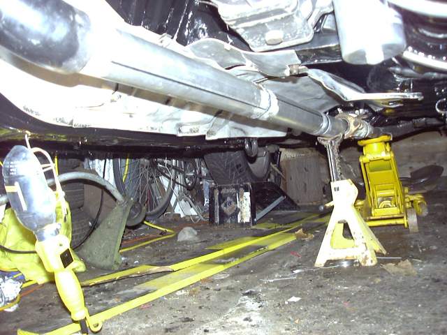
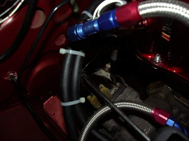
Here's a poor view of the turbo water lines, the downpipe and the O2 sensor location. I'm just using an old narrowband sensor for mockup and the initial start. In general I tend to start with a narrowband and then move to a wideband when the car is no longe running pig rich. It prevents fouling out the much more expensive wideband during the initial rough tune.
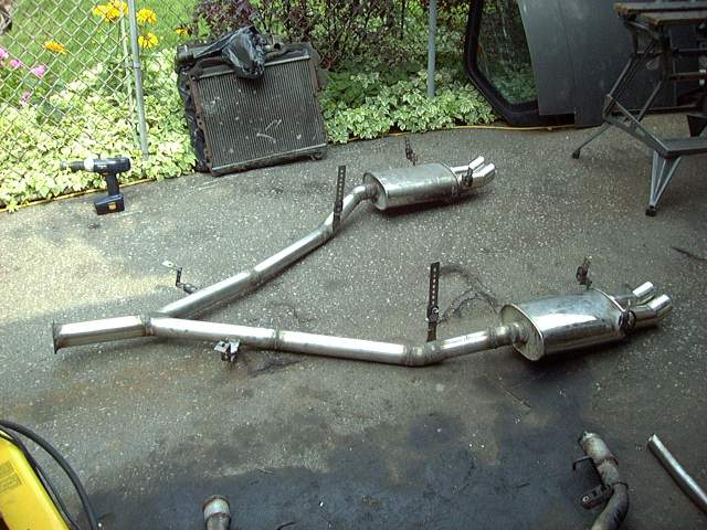
Now that the downpipe was done I could continue on with the exhaust. My old and abused 2.5" catback had taken so much over the years that when I did the original turbo-NA project I actually had to replace it with a spare stock catback and weld on my stainless mufflers. Needless to say that awful thing had to go. The new catback is also 2.5" but made of 304 thick walled stainless.
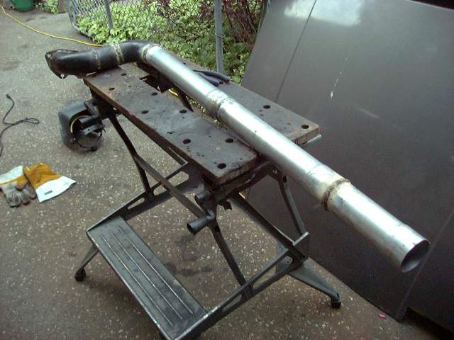
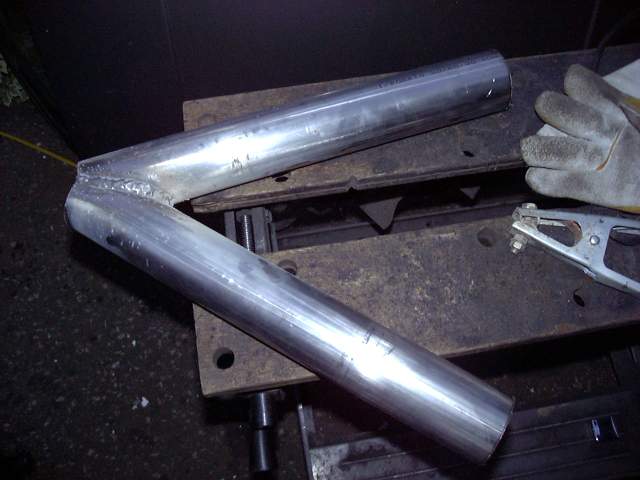
First, the Y pipe had to be created. The temporary downpipe was made with a 3" 3 bolt header style flange, so I welded the same style flange to a foot long section of 3" stainless tubing. The flange is temporary as when I make the "real" downpipe (after the turbo is upgraded) I will be using a v-band setup. Two pieces of 2.5" tubing were cut and then given a 45 degree bevel on one end. Those bevels fit together to form a merge point. The resulting "V" pipe was then positioned at the outlet of the 3" tubing to get the angles right.
Here's the V pipe welded together. There is still some cutting needed at the base of the V so that the OD of the V lines up with the OD of the 3" tube.
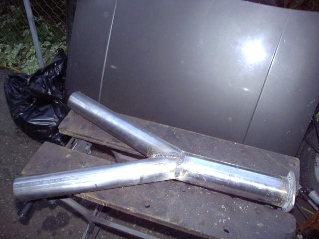
The V was again positioned under the car, tacked into place, and the whole assembly removed from the car to be welded on the bench. Once it was welded, I went into the 3" section of pipe with a die grinder and finished off the inside of the Y. It took some grinding to remove the excess material from the pipe joint and make a smooth and full-flowing transition.
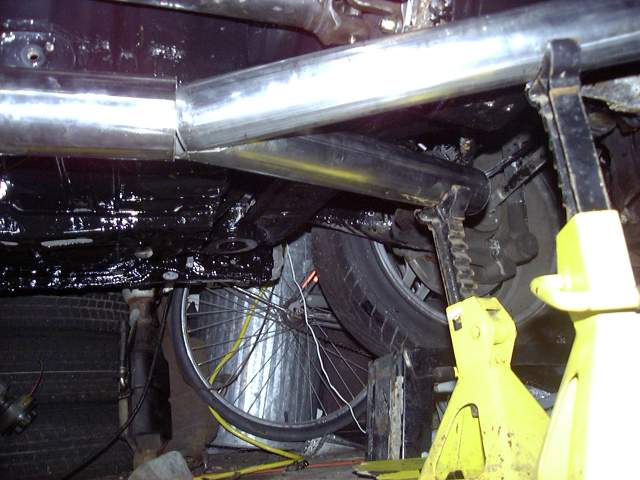
After bolting the Y pipe back onto the downpipe and positioning it evenly, the rest of the system was started. To make things easier I tried to keep the position of the bends close to the stock catback so there would not be a lot of guesswork as far as angles and positioning goes. To start the tailpipe another section of tubing was welded to the Y pipe at a slight angle. The system was then continued by using sections of stainless 90 degree weld els that had been trimmed to form various angles.
This was work that took far longer then it should have due to lack of space. Each pipe took several trips in and out of the garage which mean actually crawling under the car since there is not enough clearance side to side to squeeze by. The drivers side had to be tack welded, removed from the car, finish welded then reinstalled so the passenger side could be tacked. Finally when the whole system was done it would not fit under the car to allow it to be slid out the front of the garage since it was slightly wider then the wheelbase! So I had to jack each end of the car up, slide it under the wheels, let the car back down on the ramps, and continue...Sometimes I wonder how I get anything accomplished...
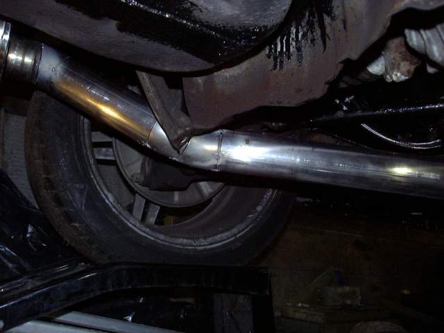
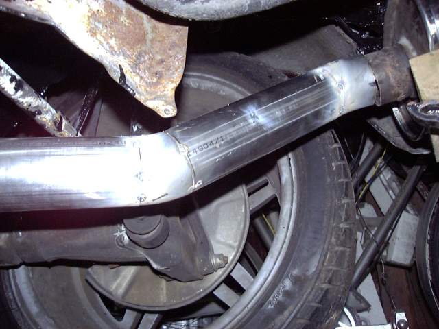
The passenger side was next. Here's the section of pipe right after the Y. For slight angles it's not really worth using the els, so I just cut the pipe at a slight angle and welded it where I wanted it.
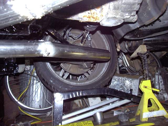
Bends at a more extreme angle would be heavily restricted if the pipe was just cut and welded (unless many cuts and many welds are made) so the weld els are useful here. I generally just get 90 degree els and then cut them apart into basically random angles. A box of those is very handy for stuff like this.
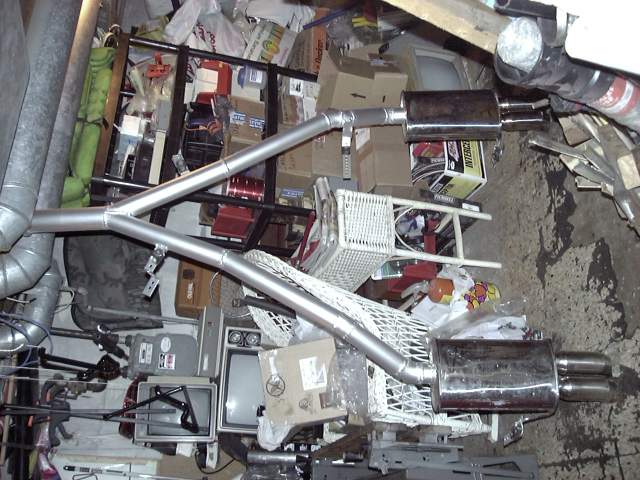
When all the tack welds were done, the system was removed from the car and then brought over to the bench to be finish welded. Here's the finished exhaust before the welds were cleaned up. I know someone is going to make fun of my mufflers but I love these things. I've had them on the car since the late '90s, long before every rice Honda had copies. They are full stainless, sound great, look great (in my opinion) and are unique on the RX-7.
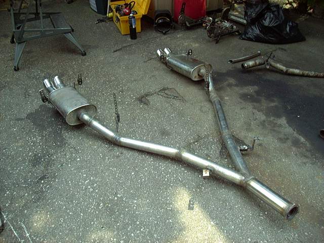
Another view of the catback. The hangers were purchased at a local parts store and are very well designed. Basically they are a section of thick rubber riveted between two steel hangers. Easy to work with and they don't rattle around like the stock rubber doughnuts. One thing that annoys the hell out of me is a car where the exhaust moves side to side as it goes down the road. These hangers keep the exhaust still but can bend when necessary (ie. when the engine torques).
Just after this picture was taken the whole exhaust was gone over with a grinder and flap wheel to remove all welding splatter and provide a rough surface for the paint to grip...
It's not often that I do something that fails utterly and completely. I'm not saying that I'm perfect or better then anyone else but I do put a lot of thought into everything I do so things tend to work out. This is not one of those times. I really thought this would work since the concept is sound but my execution was not for reasons explained below.
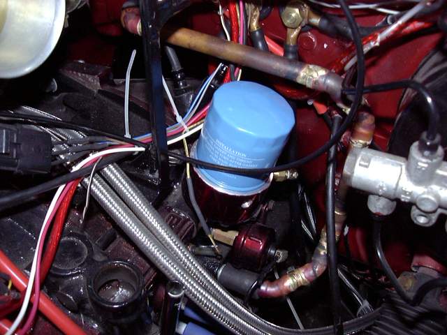
Since I made solid radiator pipes I figured I would do the same thing with the heater lines. After all, the drivers heater line is notorious for failure and the passenger line is totally in the way of the turbo. The plan was to use standard copper piping to replace the rubber hoses, so I went about mocking up the lines. Here's the passenger side line where it connects to the radiator.
Seems to fit very well.
That line ends up at the firewall just above the exhaust area. In stock configuration the rubber lines get baked by exhaust heat.
Have you figured out the problem yet?
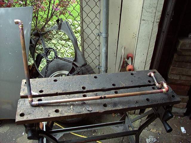
To assemble the pipes I chose to braze them. Soldering is easy and would work but the temperature at which solder mounts seemed to be a little low for an engine bay. A few pre-fluxed bronze brazing rods and a MAPP gas/oxygen torch was used after all the joints were thoroughly cleaned.
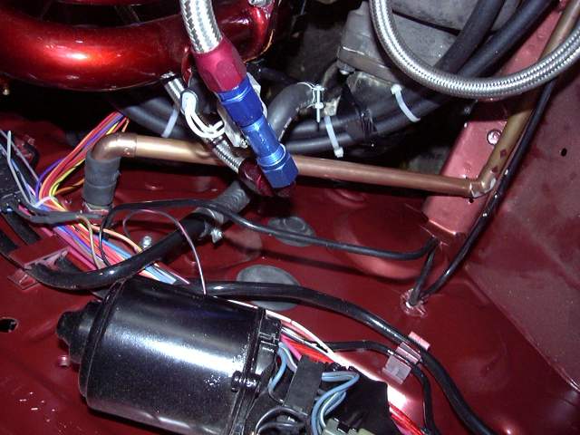
The problem with these pipes is easy to see here.
The drivers side was done in the same way but required some stranger bends. To hold things in place I was using bits of heater hose slipped over the nipples and the pipe. The plan was to ultimately use silicone couplers and T-bolt clamps, but that didn't quite work...
Once the pipe was brazed and put back into place, the problem became obvious when I tried to tighten the clamps. In using the plumbing joints as the clamping surface, I had not left enough area for the hose and clamp to get a real grip. Only about 1/2" is not enough to make a solid connection especially with slippery silicone hose. Every time I tried to tighten the clamp, the pipe just squeezed out. Even if I had managed to clamp it in the driveway, it's highly likely that it would vibrate loose after a few minutes of operation.
So if you are going to do this, leave at least 2" of clamping surface just like the stock nipples provide.
These pipes were removed, thrown into the spare parts bin and then 5/8" silicone heater line was used in place.
To finish off the exhaust I used POR-20 "aluminum" paint. Its a high temp coating from the POR-15 people that is supposed to be good to 1400F. It's strange stuff in that after it dries, it's not really dry. You can still take it off easily with your finger nail. Only after half an hour or so at 400F does it harden. Primarily I wanted the pipes to be one colour and to keep rust off the welds. This is the same paint I will be using when I make the new turbo manifold.
That's it for this update. A lot has taken place since I started writing this post so in the meantime the exhaust has been bolted to the car, a bunch of wiring work done, gauges installed and the intercooler is currently being mounted. Very soon I should be starting the car so the excitement builds...The plan is to break in the engine during the remaining summer months, then deal with upgrading the turbo over the winter as well as finishing the interior. Probably a quick trip to the body shop to sort out a few issues, suspension in the spring and then it's done!