| Home > RX-7 > My RX-7 > Project Tina > Project Tina, August 7th, 2006: Fuel System, Intake Manifold Installation, Exhaust Fabrication |
| Home > RX-7 > My RX-7 > Project Tina > Project Tina, August 7th, 2006: Fuel System, Intake Manifold Installation, Exhaust Fabrication |
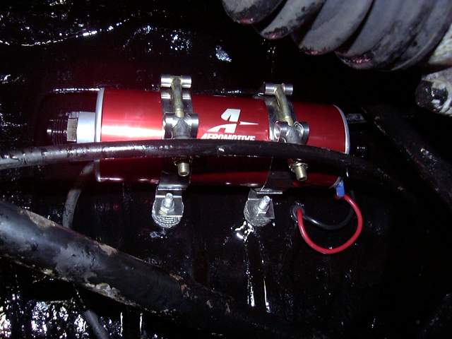
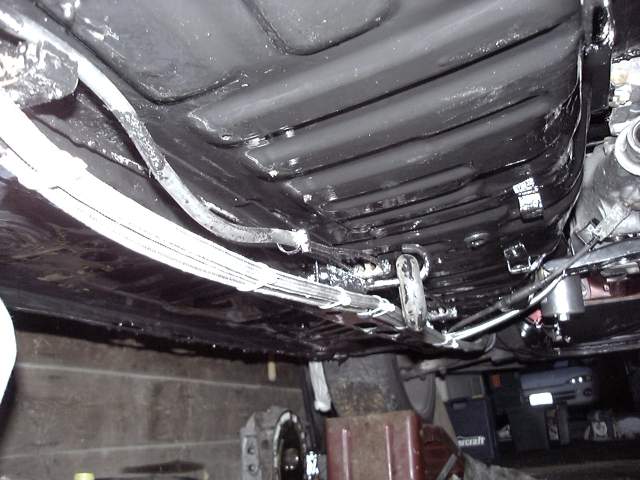
The fuel pump was mounted on the underside of the drivers storage bin/rear seat cavity. These pumps tend to be a little loud so I inserted toilet tank washers between the clamps and car to try and keep it quiet. It's still a huge pump so it will definitely make noise. If it gets bad, I'll just wrap the pump in Dynamat. The pump offers a -8 ORB inlet and -6 ORB outlet. Adapters were used to turn those into AN flare fittings.
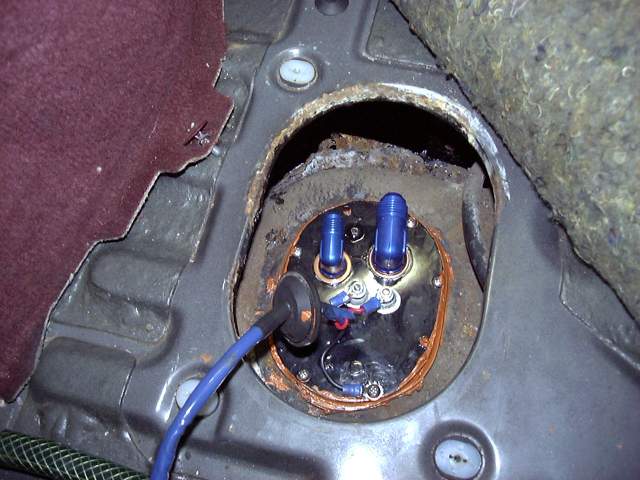
After the pump was mounted, the fuel flange was installed on the tank. To my surprise it actually fit. A new gasket and orange silicone goo seal flange to the tank. I'm a bit worried about this whole arrangement since it means the pump must draw the fuel out of the tank. Conventional wisdom says that these pumps should have a gravity feed inlet with the pickup mounted as low in the tank as possible. So I may experience suction problems when the fuel level in the tank is low. If that's the case, I'll pick up a brand new tank from Mazda and add a sump with some external bungs. No way in hell I'm going to attempt to weld on a tank that has held fuel.
And then the lines get installed. The thick -8 line is feed to the pump while the thin -6 line is return from the regulator.
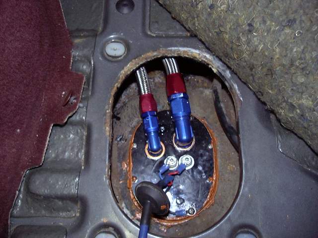
Here are the lines connected to the pump. Space is tight but luckily AN fittings come in all kinds of weird sizes, including 120 degree swivel...
Also notice the ever important rubber grommet where the power wires pass through the sheet metal, and the dielectric grease on the connections.
The fuel lines just fit between the differential mount and the frame rail.
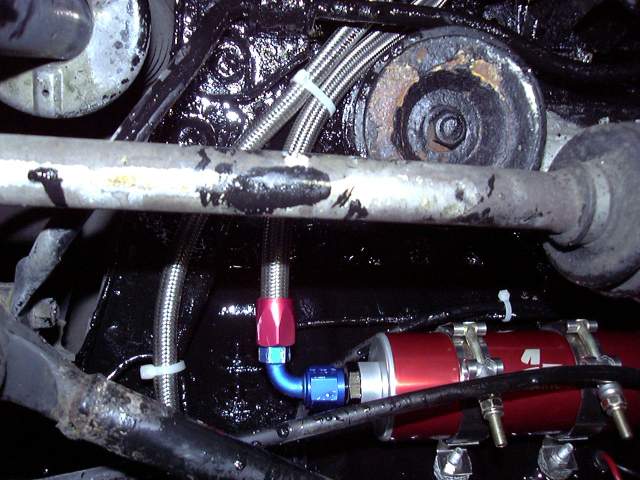
Rubber insulated hose clamps secure the lines along the bottom of the car and zip ties keep them from rubbing. Braided stainless will abrade through anything, even POR-15, so it's important to keep them from wiggling around.
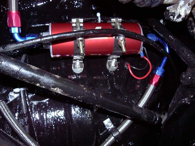
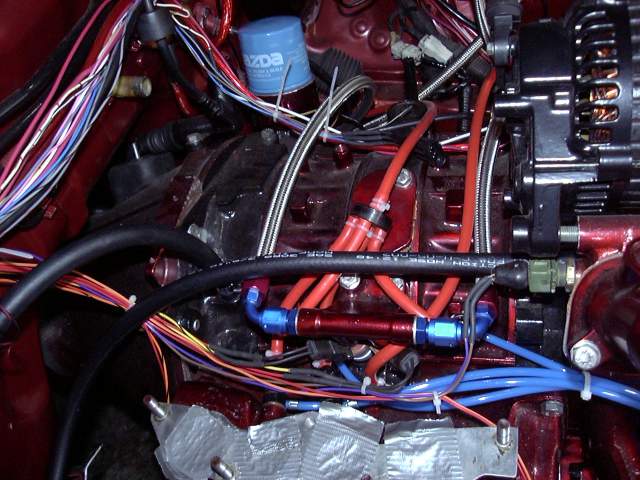
Now that the fuel lines were run to the front of the car, the connections could be made to the fuel rail. The NA fuel rail has a M12 x 1.25 thread on each end. Note that this is different then the turbo rails as they have an M14 x 1.5 thread on one end. Two Earls Delorto carb adapters were used. I was pleasantly surprised to find that these adapters come with Dowty seals to prevent leaks. I went a step further and also used Teflon sealing compound on the threads.
One side of the rail goes to the feed from the filter (left in the picture) while the right side of the rail heads up to the pressure regulator. Note the return line at the bottom of the regulator that goes all the way to the back of the car.
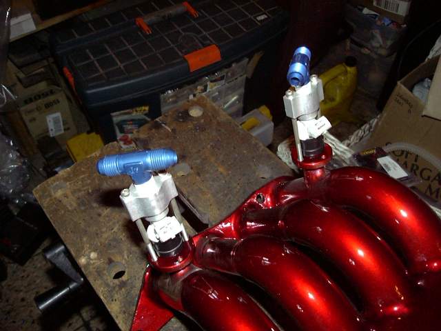
At this point my 1680CC injectors arrived at the local Ford dealer and I couldn't resist installing them. The ATP Turbo injector holders have a 1/4" NPT port at the top so I used -6 AN tees with 1/4" NPT threads on the bottom to make the fuel connections. The electrical plug was turned towards the intake to help keep it out of exhaust heat. If I had been thinking when I designed the intake, I would have mounted the injectors on the inside of it facing the engine instead of on the outside facing the exhaust. Oh well...
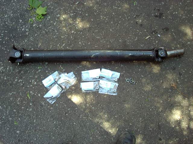
This is the reason I tell people to go to the local driveline shop. I had my driveshaft rebuilt with brand new u-joints, had the front yolk polished and the rear yolk replaced. The u-joints are replaceable and have grease fittings so they won't wear out in the future. The cost? Nothing.
I also stopped by the Mazda dealer and picked up new driveshaft hardware since mine was pretty rusted and worn.
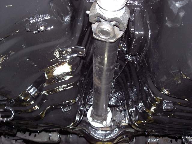
The driveshaft installed without incident. Anti-seize was applied to the differential flange to prevent rust, while the front yolk was coated in Vascelene to prevent damage to the seal upon insertion.
My old metering oil "vacuum" spider was looking pretty sketchy, so I replaced all the old rubber with new silicone hose. This "vacuum" spider is actually an air supply to the nozzles. It connects to a fresh air source before the throttle bodies which insures that engine vacuum always draws oil through the injectors.
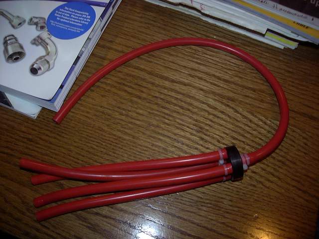
Here is the air spider installed as well as the air line to the primary injector air bleed. Don't leave the injector bleed line out because the air jet shooting at the injector really helps atomize fuel and drastically improves idle quality.
I wish Mazda had more evenly spaced the oil injectors so my hoses would be even on each side of the fuel rail.
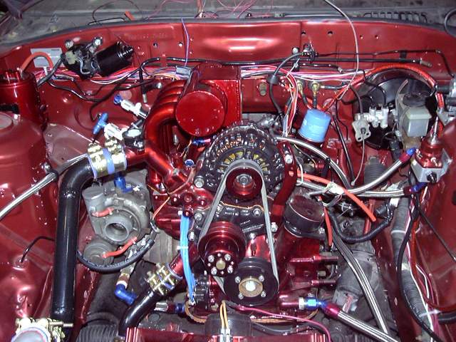
The black coolant hoses from the rear iron and water pump housing are water supply to the turbo. I used fuel injection hose because it easily handles the pressure, is easy to bend and I'm not sure if the upgraded turbo I end up with will need a water supply so I didn't want to waste time and money on braided stainless and AN.
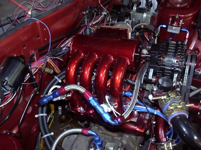
The moment of truth! At this point all the work on the top of the engine was done so it was time to install the upper intake manifold. I had to run a die down the stock lower intake manifold studs to increase the amount of thread available but besides that it fit perfectly. I was very, very relieved to find that the hood still closed. I also snuck the dual belts on before I installed the intake.
Another view of the intake manifold.
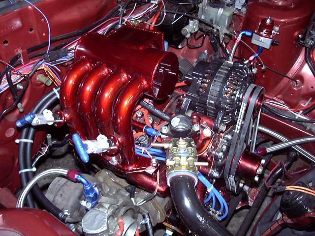
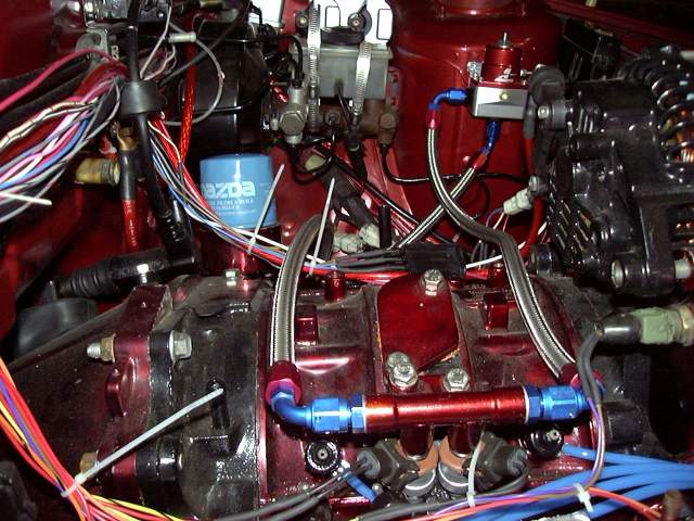
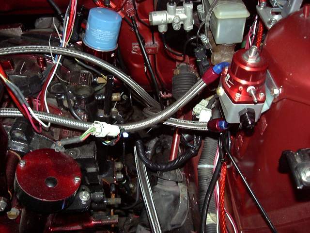
With the manifold in place, I could make the fuel lines. On the left, the feed line goes to the fuel filter under the car. The right line leads back to the pressure regulator. The little middle line was a bit of a pain because I could not come up with anything better. The only other option was to make a metal line but it would be very difficult to install due to it's ridgitity. This line was relatively easy to install but it is also the highest point in the fuel system and in a warm area. I'm really hoping that vapor lock won't be an issue. It shouldn't, since the lines are under pressure (which raises the boiling point). If I have issues, I'll mount a fuel cooler along the frame rail.
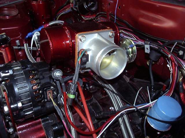
The Edlebrock throttle body installed easily with the supplied gasket and a bit of gasket goo to assure a good seal. You can see that there is a actuator cable attached to the spool. This is NOT the throttle cable, but the cable to actuate the metering oil pump. More on that later.
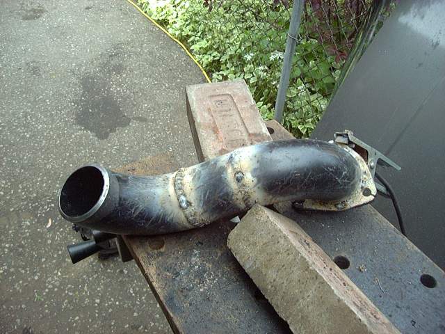
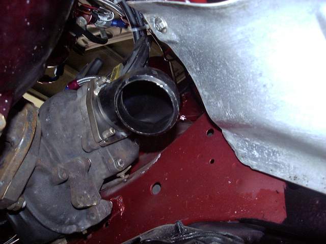
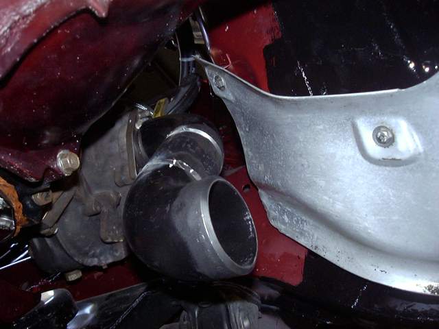
Time to make a downpipe. I started with a turbo flange from Mazdatrix and some SCH 40 weld els from the local industrial plumbing supplier. These els are very cheap, nice and thick and easy to work with. I prefer a thicker downpipe because it doesn't have a "pingy" noise and helps keep the heat in the pipe and out of the engine bay. It's a little heavier then most of the aftermarket downpipes but in my mind I would rather have a few more pounds then deal with the noise. And it will last forever, even though this one is just temporary as I'll have to make a new one when I switch turbos.
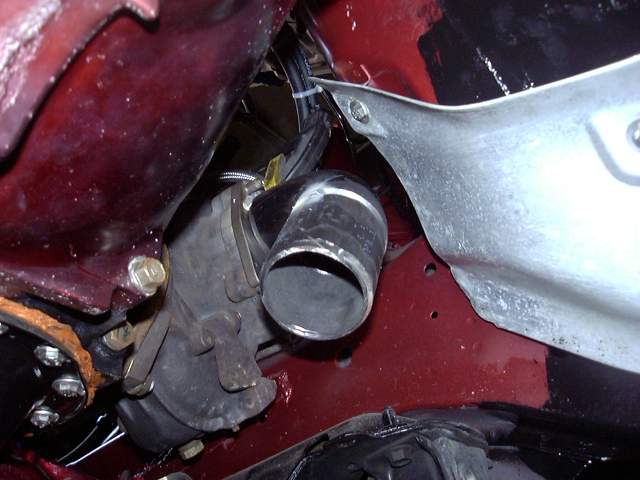
The first step was to tack a 90 degree el onto the flange. I'm using 2.5" here.
Then a 4" section of pipe to extend the pipe downwards. Notice the bevel on the joints. This assures good weld penetration and also eliminates grinding.
Another 90 degree el was tacked into place.
And then the whole mess was finish welded on the bench. Not too shabby welding job, eh?