| Home > RX-7 > My RX-7 > Project Tina > Project Tina, January 11th, 2006: Upper Intake Manifold Fabrication, Coolant Pipe Fab |
| Home > RX-7 > My RX-7 > Project Tina > Project Tina, January 11th, 2006: Upper Intake Manifold Fabrication, Coolant Pipe Fab |
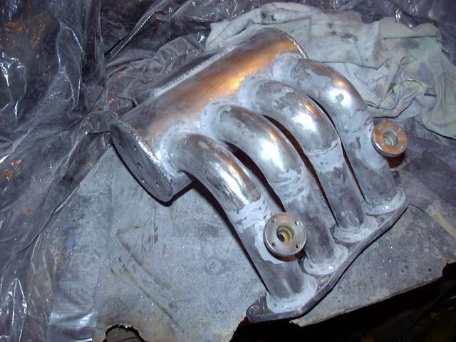
Most of the welds on the runners were ground down almost flat to make the runners appear smoother. I didn't want to make the welds invisible so I left about 0.5-1MM in tact to clearly show the joints. The idea was to make it clear that the intake was hand fabricated and not bought off the shelf.
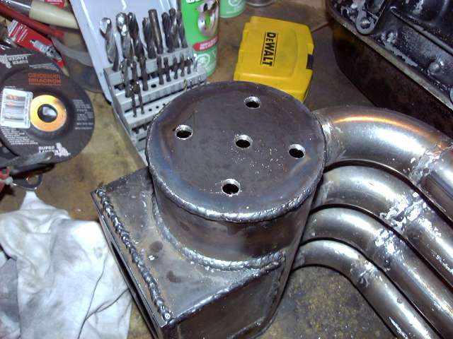
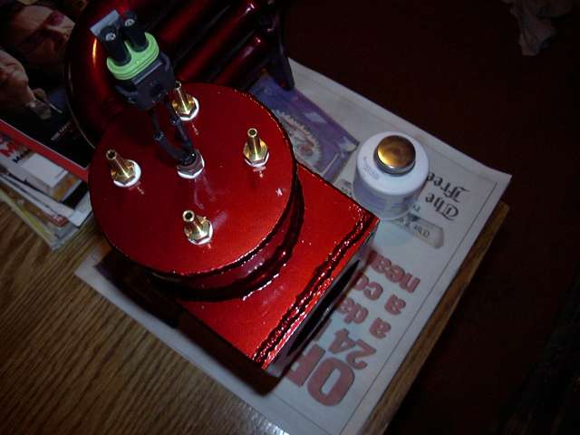
One the grinding was done there were only a few steps left until it got painted. Most importantly the vacuum nipples and sensors had to be fitted. You can see in this picture four outer holes that were drilled and tapped for 1/8" NPT for the vacuum nipples. There are only 4 vacuum lines I am planning to use: fuel pressure regulator, BOV, purge/charcoal canister and the line into the cabin for the Microtech's MAP sensor and boost gauge. As I have mentioned in previous threads I am keeping the purge system to avoid having to empty catch-cans and to prevent the car from reeking like fuel. The hole in the middle is tapped out to M10x1 for the intake air temp sensor.
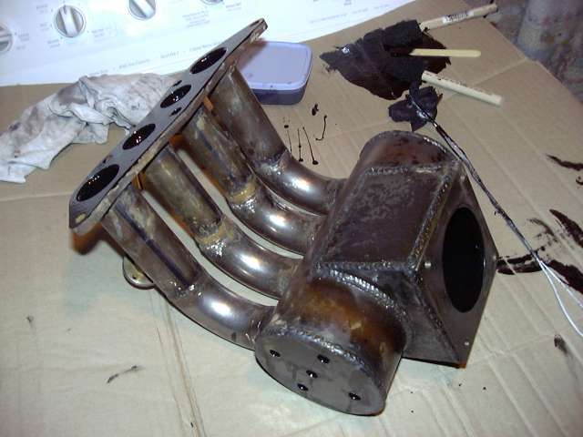
This is a very poor picture but you can just make out that the inside has been coated with POR-15. The primary concern is not corrosion, but smoothness. POR-15 dries to an almost glass smooth surface when applied properly, perfectly suitable for the inside of an intake. Think of it as a poor-man's ceramic coat. The POR-15 smoothed out all the transitions and sealed any little pockets between adjoining pieces. And the coating on the mounting flange will assure easy gasket removal in the future. You can see how the POR-15 oozed out of the vacuum and sensor holes meaning that those threads will need to be chased before final installation.
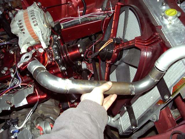
While the POR-15 dried inside the intake I turned my attention to another small fabrication project. Having a few extra weld els left over from intake making I decided to make metal replacements for the stock rubber radiator hoses. It only took a little fitting and about half an hour before the upper hose was tacked together. The next two images show that pipe compared to the stock hose.
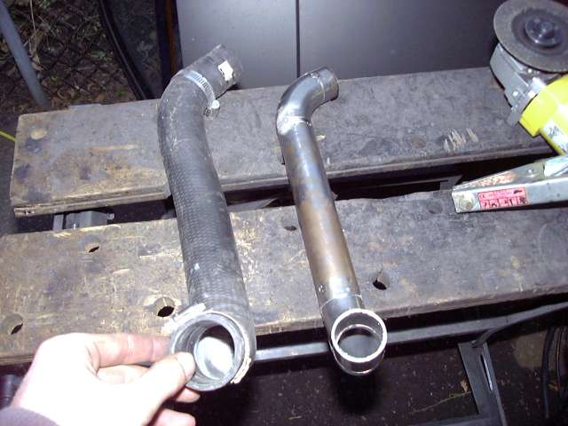
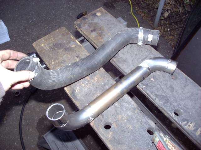
Test fitting the upper radiator pipe. It worked out perfectly. To connect it to the engine and radiator, 1.5" silicone couplers with T-bolt clamps will be used. Unlike the worm gear clamps, T-bolt clamps will not cut into the hose. The downside of course is that they are about 10x more expensive and hard to find in small diameters. I guess it's also a good time to mention that the alternator shown in these pictures is purely for mockup purposes as I'll be picking up an FD unit from silverrotor.
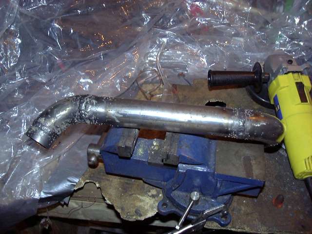
After the fit was verified the pipe was finish welded and checked for leaks.
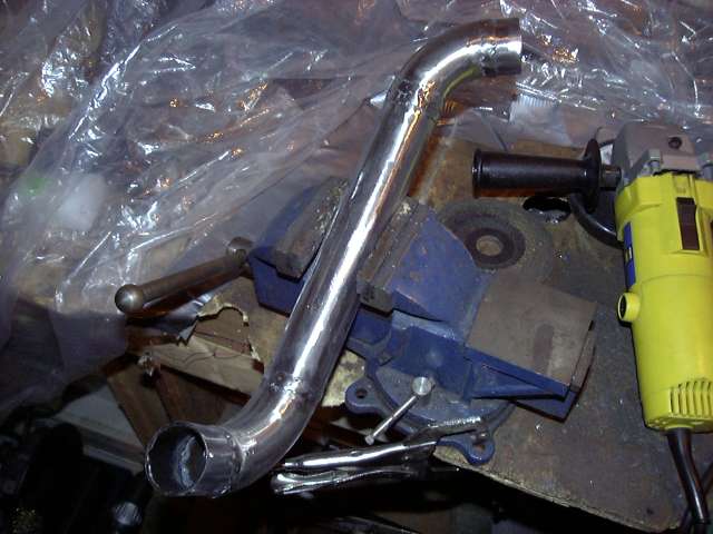
The final step before it was prepared for paint was to finish the surface with a flap disk. Again I didn't take the welds down totally to show that the pipe was hand made. I mainly just smoothed them out and removed the splatter left by the flux cored wire. Flap disks are great for this.
Now back to the intake.
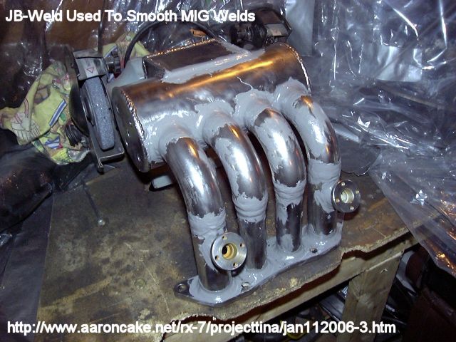
Once the POR-15 dried, the outside of the intake was cleaned up with a wire wheel to remove any crud, rust, oil and welding debris left over. I decided that I would coat all the joints with JB-Weld to eliminate the possibility of pinholes. With this much welding done in tight areas and no way to pressure test the intake I was worried that there might be one or two areas that could cause trouble. I'm not a JB-Weld abuser. I hardly use the stuff so I was actually a little reluctant to post this picture since it makes the intake look like only JB-Weld was used to stick it together. Rest assured that the JB-Weld was only used as precautionary measure.
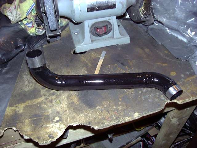
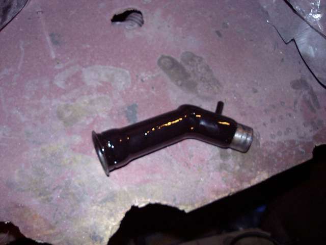
I had to let the JB-Weld cure for a few days so in the meantime I painted the upper radiator pipe with VHT's Black Caliper Enamel. I use this stuff on anything I need to paint black since it forms a very tough surface that is chemical resistant. Especially after it is baked. The inside was coated in POR-15 to prevent corrosion.
After some sanding (yeah, like 3 days of it) the JB-Weld was smooth and ready to paint.
At this point it's also worth mentioning that I did have to do a good amount of grinding on the inside of the intake to smooth down any rough spots and welds. Every wonder what that long flexible attachment on the Dremel is for? It's for exactly this purpose. Getting down into the runners was actually very easy with that tool and an appropriately sized stone.
The intake was painted by first laying down 4 coats of MetalCast Base, and then 4 coats of MetalCast red. There were a few tight areas but for the most part it turned out well.
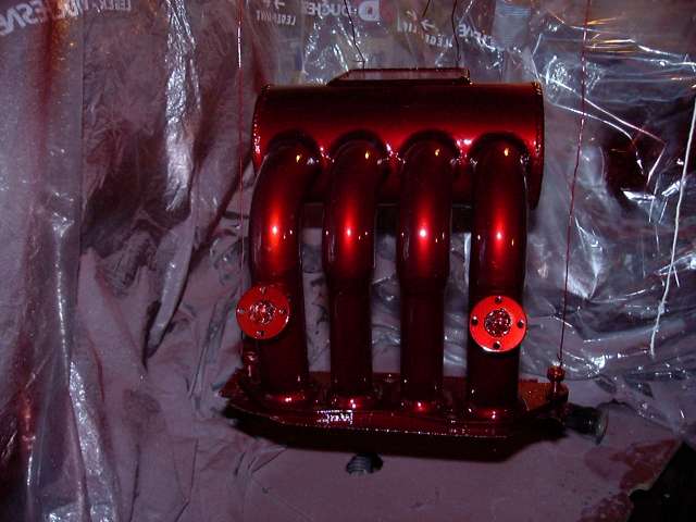
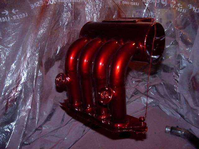
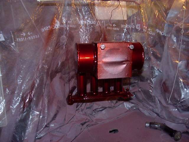
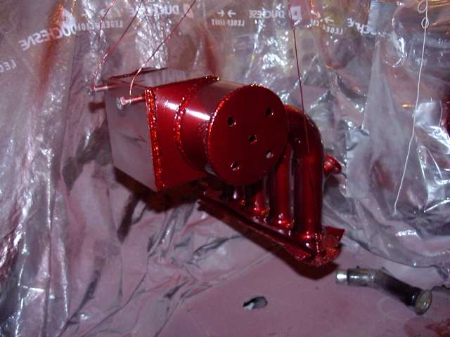
After the paint was fully cured (about a week) the air temp sensor and vacuum nipples were installed. Because these are straight pipe threads instead of taper, sealing is important. Liberal amounts of brushable Teflon sealant was used and the fittings all tightened until they bottomed out. Notice the connection to the air temp sensor has been modified to use a WeatherPack style connector. The leads of the two pin WeatherPack connector were simply soldered to the terminals of the sensor and then adhesive filled heatshrink use to seal the whole mess. This will be much better then the stock connector that is completely exposed to the elements.
As I mentioned previously, the tall straight NA oil filler neck interferes with intercooler piping to the new intake. To rectify this I just cut the bottom off, tilted it and then welded it in place. The void was then filled by a small section of tube. It's not the prettiest thing in the world, but it will work. Yes, I could have just used the TII oil filler neck...but what's the fun in that?
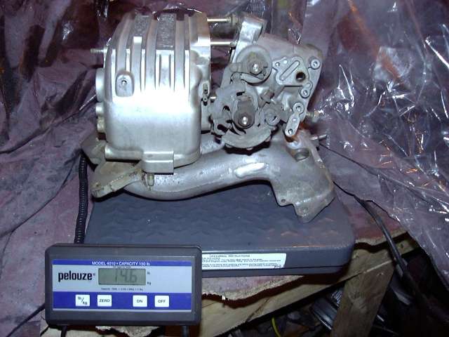
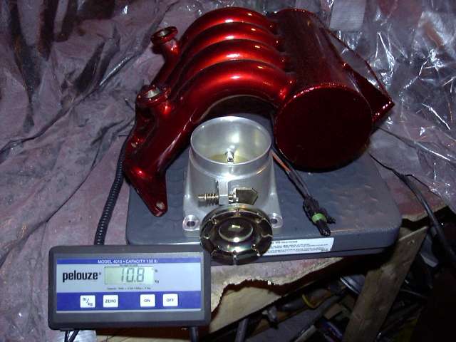
Because I know that there are many people out there about to ask "Why didn't you make it out of aluminum/titanium/carbon fiber/unobtanium? Steel is so heavy! Whine!" I figured that I would compare the weights of the stock NA aluminum intake to my steel intake.
As you can see below the stock NA upper intake assembly weighs in at a hefty 14.6 LBS. And this doesn't even include the fuel rail, bolts, emissions hardware, TB spacer or mounting brackets.
In contrast, my steel intake and throttle body weighs a feather-light 10.8 LBS. Even though the stock intake is aluminum it's castings are much thicker due to the manufacturing process and thus it gains quite a bit of weight.
And the intake manifold is officially done! Wow, that was a lot of work. It took 1.5 months of working several hours a day to get it completed and I'm pretty happy with the results. Even though I'm happy, I'm planning to make another one in the future to deal with some of the design problems I have already noticed in this first attempt.
Specifically, things I would do different are:
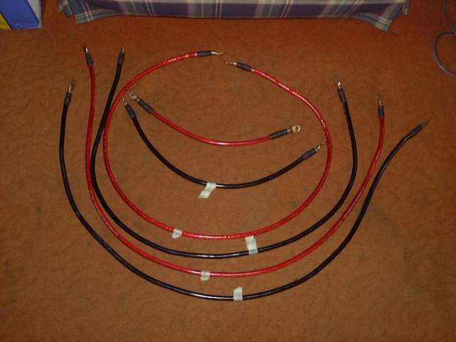
The final picture shows all the high current power cables used in the car (except those that go to the battery). They are all 4 gauge wire. Lugs were purchased at a welding store and then soldered in place. Before heatshrink was applied the end of the cable and solder joint was packed with dielectric grease and then the heatshink was shrunk around the joint. This will make a very reliable cable. Initially I purchased a bunch of lugs at a local auto parts store. Once I started working with them I saw how indaquate they would be and went for the welding store lugs. Good thing I did because not only were they WAY cheaper (70 cents a piece of the welding store lugs compared to $2.99 for 2 auto pats store lugs) but twice as thick and made of much higher quality copper.
The two short cables inside the circle are power and ground to the starter. The next red one carries power to the engine bay fuse box. The next two black and red cables carry power and ground from the electrical panel (ECU area) to the firewall passthroughs. And finally, the outer black cable is a ground cable between the firewall passthrough and drivers frame rail (stock grounding point). This grounding point is where I have also grounded my Crane HI-6 and electric fan. Another ground will likely extend from that area to the front iron of the engine for redundancy.
This thread represents the last major fab project needed to get the car running. Only a few minor things remain. These include throttle cable bracket, intercooler mounting and piping, downpipe and a few other things. All of which are very simple. For the next few months I'm going to be laying low working basically stockpiling parts and working on a 12A peripheral port side project I'm eager to get going. Next on the list is making a lower rad pipe, creating a fuel pump bracket and perhaps mounting up the intercooler.
It's likely this will be my last thread until spring at which point a lot of progress will take place very quickly.