| Home > My Projects > Craftsman 5/22 Snow Blower |
| Home > My Projects > Craftsman 5/22 Snow Blower |
Date Of Project: Summer 2018
I'm going to be the first one to admit that I have a strange, call it interest, or maybe even fascination with snow blowers. Let's keep it below obsession though. It stems from the fact that as kids, every winter I started harping on the parents to acquire a snow blower. It never seemed like a valid use of anyone's time to shovel the driveway at every snow fall, taking up to an hour or so, when there was a machine which could do the work in 10 - 15 minutes. Plus the fact that my brother and I had wanted to expand our summer lawn care business to winter snow clearing, and while we couldn't foot the bill of a snow blower ourselves, we would have been happy to pay maintenance, usage and running costs of a parental owned unit. Sadly though, it never happened. It was "unnecessary", or shovels worked fine, my mom's refrain "I enjoy clearing the snow".
 Fast forward my childhood, past my teenage years, into adulthood, all the way to the summer of 2010. When my mom called me she barely got through the sentence explaining that a neighbor was throwing out an old snow blower, and wondered if I wanted it, before I started screaming "Yes!" into the phone. Naturally it didn't run, but did I care? Nope. Even if the engine was totally trashed I had several spare engines, or there was always the option of a big electric motor, or simply rebuilding what was there.
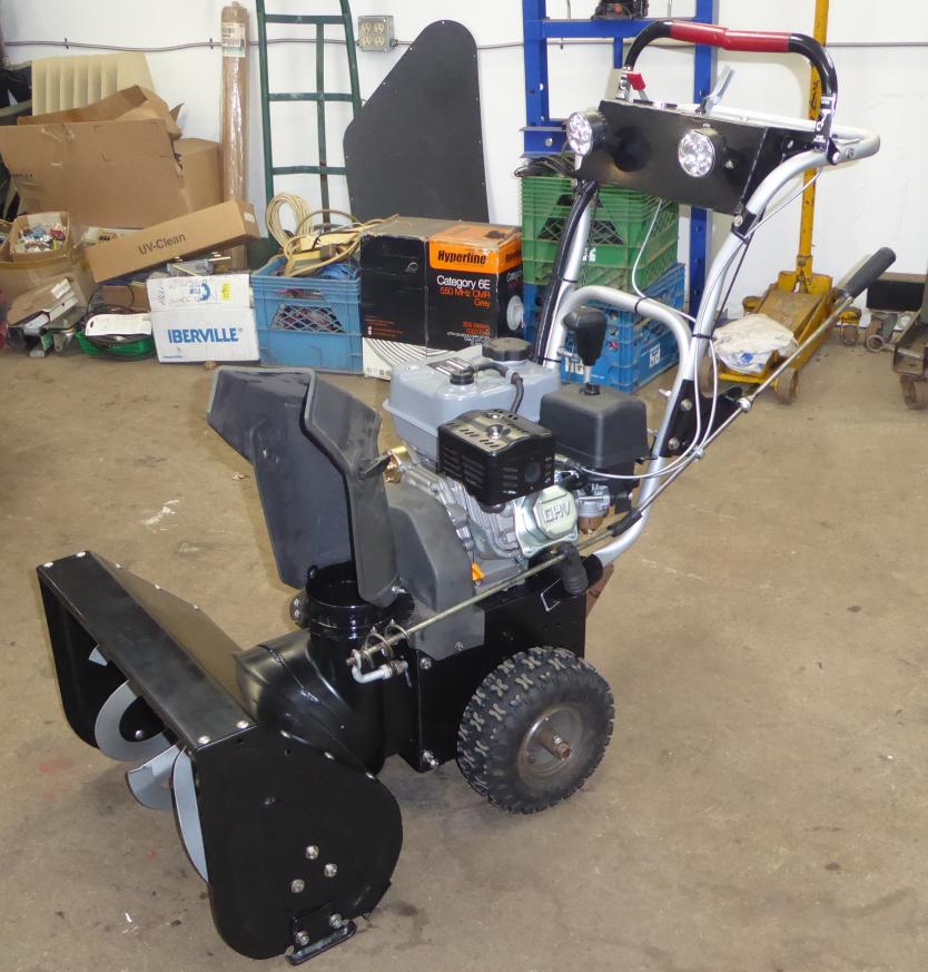
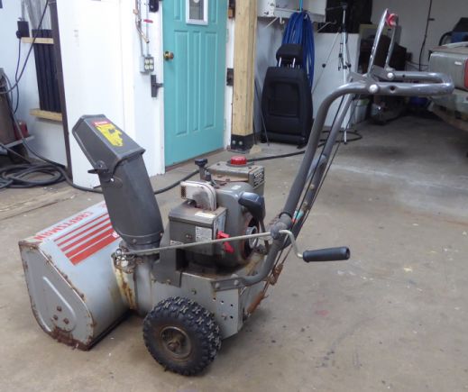
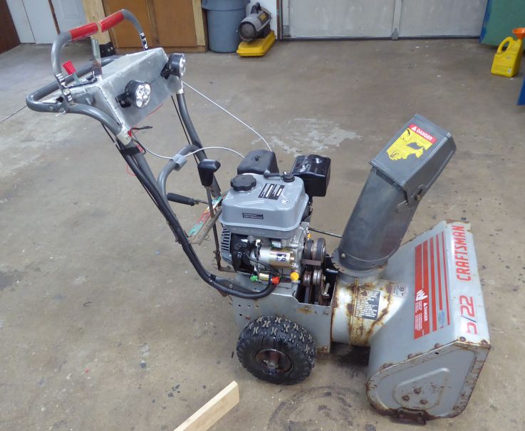
The rest of the day at work was long, after which I drove directly to my parents house and was delighted to find my prize! A Craftsman 5/22 snow blower. Powered by a venerable Tecumseh HSSK50 195cc 5HP "Snow King" engine. The engine spun over, made compression and spark, but of course wouldn't start. Judging by the smell in the fuel tank, whatever fuel was once gasoline has become varnish and quite likely that was an event which occurred every summer. The carburetor bowl drain passed a thick rust coloured goop. Well there's your problem! Shooting some fuel down it's throat fired it up without issue, so mechanically the engine would run.
Brought it over to my shop and after the installation of a carburetor rebuild kit and plenty of clean up, it was back up and running. Nothing more to do then but change the oil, put in a new spark plug, adjust the carb as well as possible then wait for snow. And wow, did we get snow. That winter was probably the most snow-filled one I can remember. One weekend in particular saw 36" of snow in a matter of a day. But it provided the perfect opportunity to adjust the carb under real world conditions and after some tweaking, the blower worked perfectly. It saw a lot of use that winter. Clearing the driveway, the neighbors driveway, the shop parking lot. And considering the use it received, it was sort of remarkable that the only failure was a broken recoil starter. Even ran the original belts!
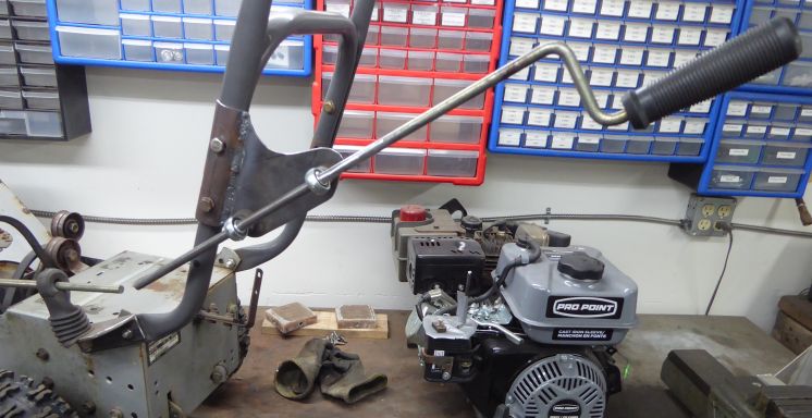
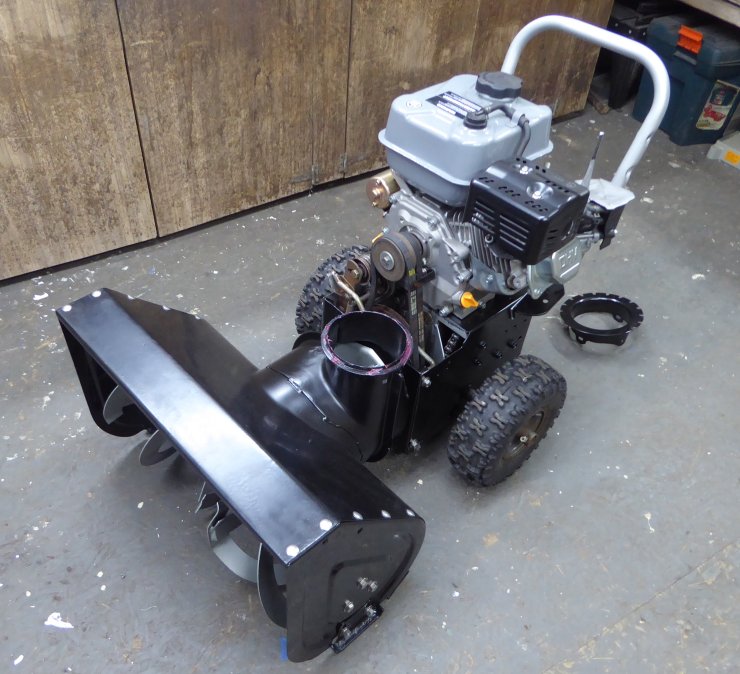
Fast forward 8 years to the spring of 2018. As I started the blower to begin the preparations for summer storage (fuel stabilizer, fogging oil, oil change) the recoil starter was left dangling from my hand. Damn it. Add that to the list. I had kind of wanted to work on it anyway to add a few features like electric start, small alternator, lighting and controls. Turns out at that exact moment, Princess Auto decided to put on sale their Pro Point 208cc OHV Gas Engine with Electric Start, knocking $100 off the price. So why fix a recoil when I can just swap the whole engine and end up with an electric starter and 2 extra horsepower as a bonus?
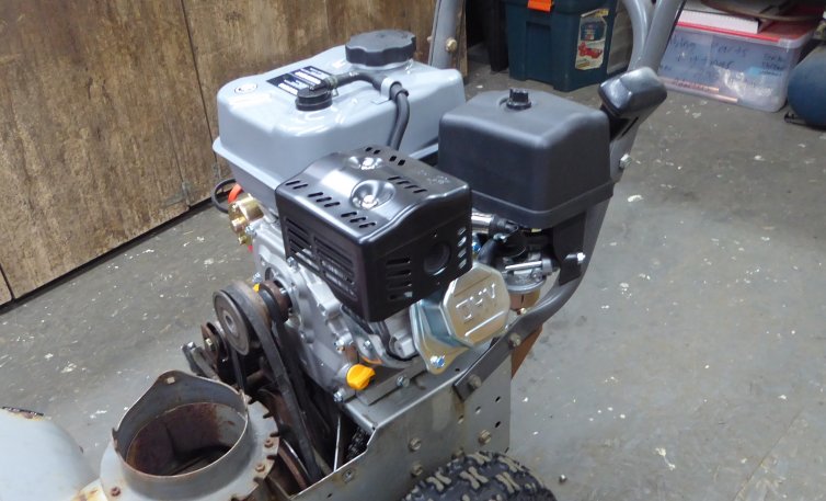
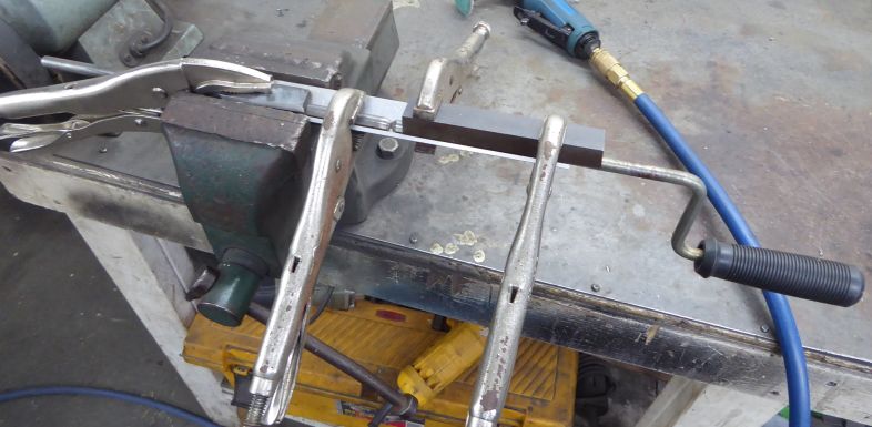
Well, that was easy. As most small engines share the same mounting bolt pattern, it bolted right up. The shaft diameter was the same we well. Kind of annoying to remove the pulleys from the old engine due to not wanting to move after 20 years. I broke my puller trying, accidentally bought a puller too big to replace it, then finally got it off with the correct sized puller and an impact gun. Of course with the crankshaft on the new engine slightly lower it took 3 trips to the hardware store to find the correct belts.
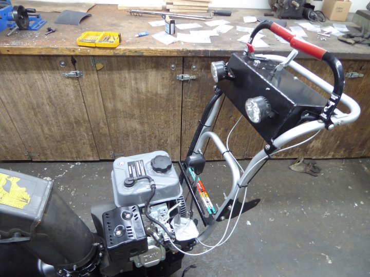
With the new engine installed, time to start on that console. I was sort of sick and tired of bending down to adjust the throttle on the old engine, or operate the choke, or ignition. First step was creating a mount. There were two holes already in the handle at about the correct location (probably for factory accessories) so I found some aluminium tubing having an ID of the handle diameter, halved it, drilled matching holes and bolted them in place.

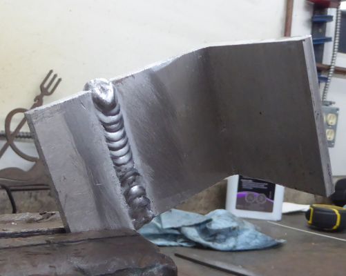
A cross member was made from some 1" aluminium square C channel, 1/8" wall. The openness of the C was needed to allow access to the bolts. After contouring the ends of the C channel to match the radius of the handle it was welded in place. Pardon the slightly messy TIG welds; this is the first time I had TIG welded aluminium in about 2 years and I was slightly out of practice.
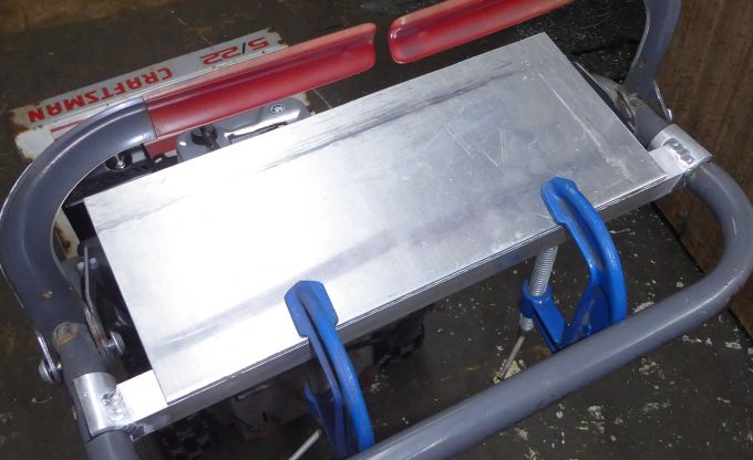
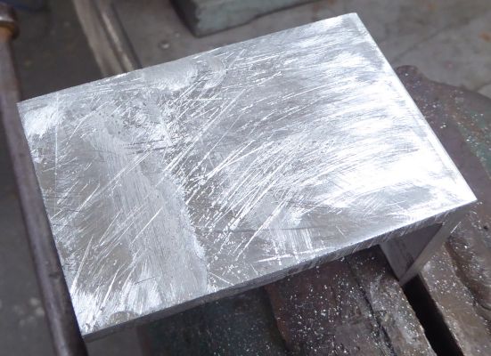
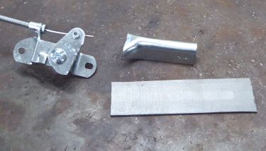 To form the console, a sheet of 1/4" aluminium was cut then clamped in place for mockup. I don't have a picture of the next step which was to drill 3 mounting holes however you'll see those holes pretty soon. Of course one of the goals with a console like this is to move all the controls up to the user. Meaning throttle, choke, ignition and starter in this case, then whatever ends up being added in the future. I picked up a generic set of throttle controls from Princess Auto in two styles; a "deluxe" throttle lever and a universal lever style control. The idea being that the "deluxe" throttle lever is marked with speeds and has a decent flange, so it will be used to control the throttle. The cheaper all metal lever is going to have to be hacked up a little and it will be used to control the choke. Holding the choke control up to the console plate and working it through the motions made it obvious that to mount it through the console and retain full movement would require an angle change.
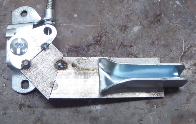
The end result when tacked together was a lever that would provide full sweep even if mounted through a slot. The original design intending to be mounted on the side of a lawn mower handle with the lever pointing out.
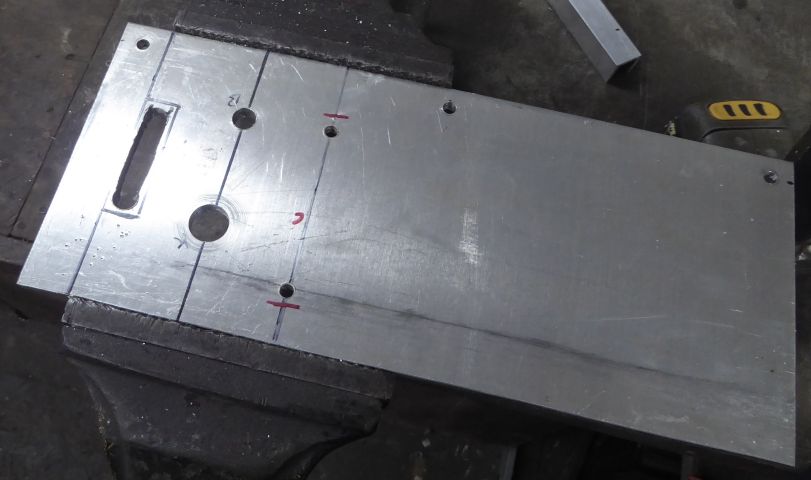
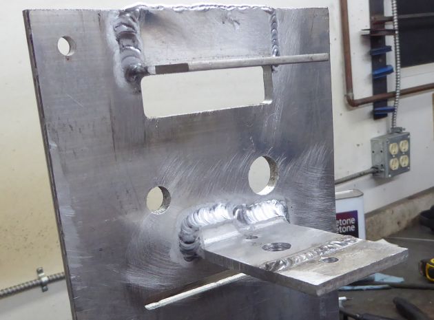
At this point, knowing how the choke lever would operate, I could lay out the console, mark the positions and drill. I rough cut out the slot for the throttle lever and drilled the end points for the choke lever. Note the three mounting holes as well to secure the console panel to the cross member.
The cutouts were then finished up on the mill. The flange on the throttle lever assembly will cover the cutout for throttle, however the choke lever slot is completely visible. So I'm slightly annoyed that I had some sort of end mill wobble which caused a slight unevenness. Guess I can go back and slightly widen the slot to even it out.
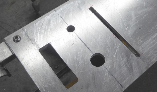
Of the round holes, the smaller one is for the circuit breaker, while the larger will mount the key switch.
As the choke lever needed a vertical bracket I welded a small extension to some 2" 1/8" aluminium angle, then milled off the weld bead on the side to which the lever would mount. After some test fitting and drilling the appropriate mounting holes, it was welded to the console.
The throttle lever received the same bracket treatment with really the only difference being the position of the holes. It was a bit more straightforward to fabricate as I didn't need to extend the angle nor was it necessary to drill a clearance hole for the pivot.
At that point all the controls could be test fitted into the console. Everything seems to fit. I did note however that I would definitely need longer screws for the circuit breaker as the added thickness of the aluminium panel means that there isn't enough screw length to reach through the panel, cover, and into the switch. Also the choke lever control cable angle is going to need a little tweaking.
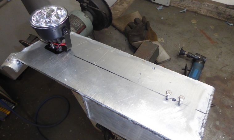
Then it was just a matter of adding a front and sides to the console. Here's the front being tacked into place. The front panel would of course hide all the mechanicals underneath the console as well as provide a location to mount some headlights. Made the front panel out of the same 1/4" aluminium, and then built the sides out of 1/8" aluminium.
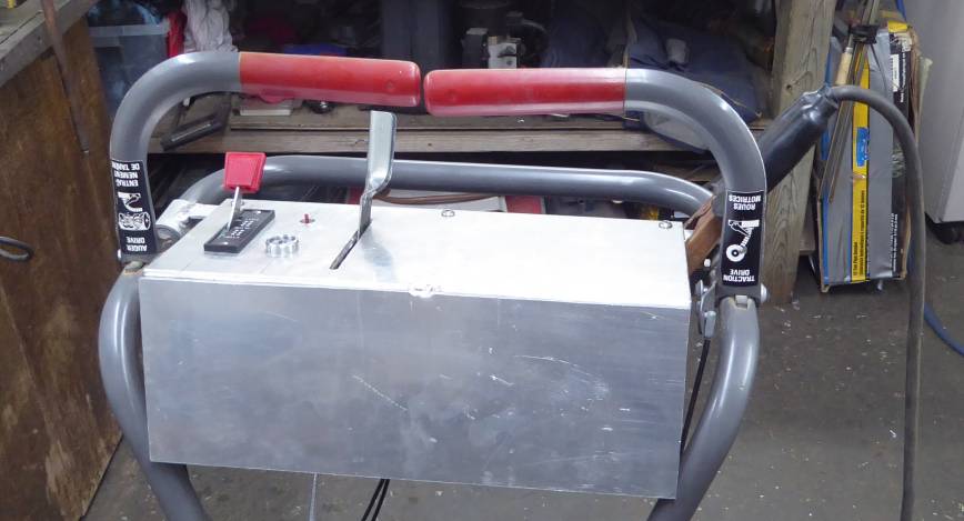
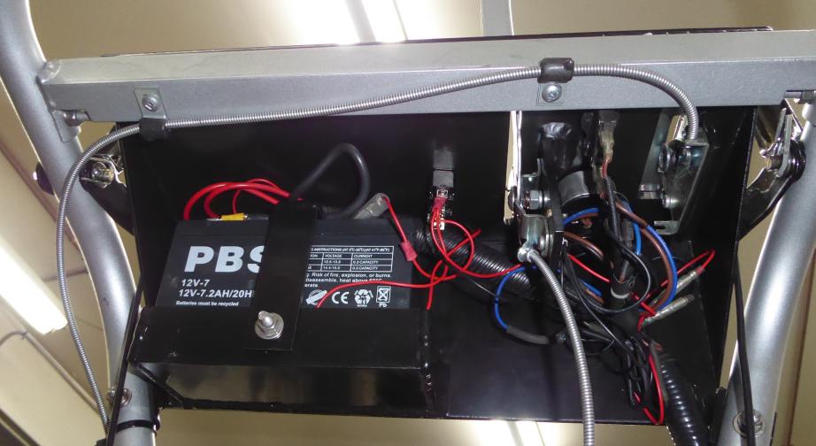
Of course in order to run the electric starter (one of the major reasons I purchased this engine) and supply power to the headlights we need a battery. I had a whole bunch of choices including R/C lithium packs, power tool batteries, or the plain old lead acid. As the 500mA charging coil on the engine and voltage regulator was already set up for lead acid, and I always have some small AGM batteries on hand, I decided to go with the easiest choice and mount a 7AH 12V battery underneath the console.
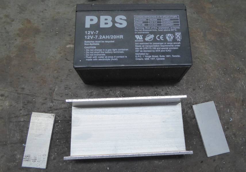
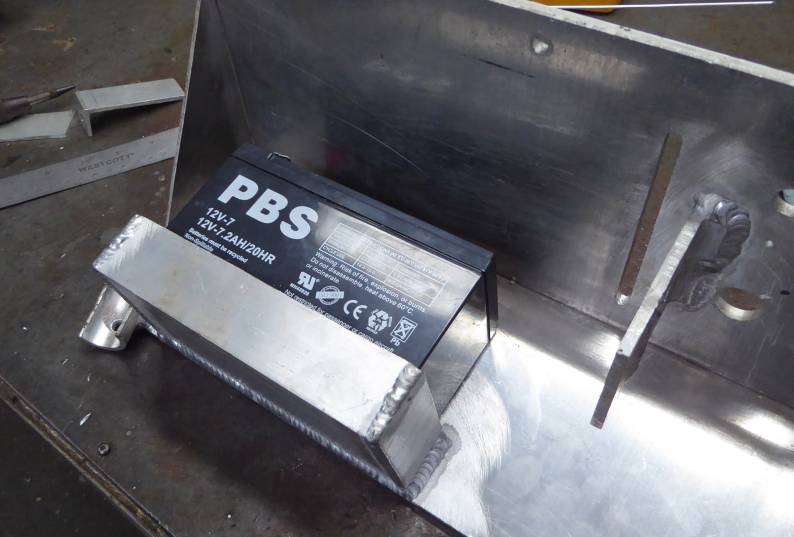
A battery tray is needed to secure the battery in place. Very conveniently I happened to have some rectangular aluminium tubing with the same width as the battery. Ran it though the band saw to cut off the top and make it into a tray, then just cut some end caps from 1/8" aluminium.
Once all welded up, it was then welded to the front panel of the console. Note also that the sides have been installed, as well as two more flanges to allow bolting of the console to the handle.
1/4" aluminium is rather thick for a console and certainly I could have used thinner material. The thicker aluminium however allows drilling and tapping. Which is how the front of the battery hold down is secured. Simply drilled a hole through the front of the console and tapped it for M6.
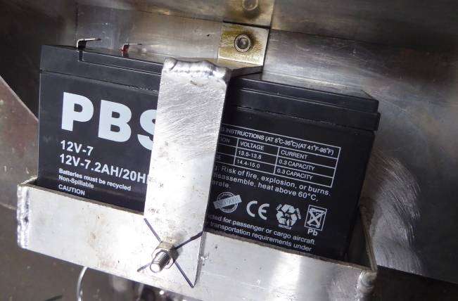
The tray side of the hold down strap is secured with a pan head M6 bolt. A little bit of a pain to access the head which means that it must be tightened via the nut. Friction between the head and tray is your friend here. If I had been thinking, I would have drilled the hole a little smaller and tapped in some threads.
This engine comes equipped with a 500mA charging circuit which is pretty useful of course for not only charging the starting battery, but running a few small accessories. Lighting is important not only to see what you are trying to do (I have a reasonably long unlit driveway) but also to let others know that you are there.
Princess Auto to the rescue again which a cheap set of "LED racing lights" on sale. These no longer appear to be in the catalogue however at the time I believe I paid about $15 for the set. Not the greatest quality but fairly bright with a slightly blue cast light. Came with a wiring harness which I adapted and shortened.
It was just a matter of drilling some holes in the console and tapping for M4. The bolts needed to be trimmed to end up flush with the interior wall of the console. One nice thing about the lights are the slotted brackets which allow some adjustment. The hole between the bolts allows the power wires to pass though.
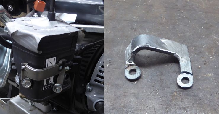
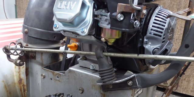
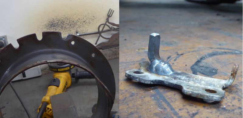
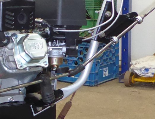
Back to the choke, this time the engine side. The choke lever on the engine provided no way of being remotely cable actuated so a bracket was needed to mount the cable. I happened to have some 1/2" steel bar stock so I first milled out some countersinks for the bolts, then bent it in the vice to follow the contour of the carburetor housing. A few pieces were welded together then the welds smoothed out.
Once all welded up, a hole was drilled and tapped out to M5 for a bolt to secure the cable clamp. To construct a simple cable clamp I just ran an end mill through a square chunk of steel to create a channel then drilled the bolt hole.
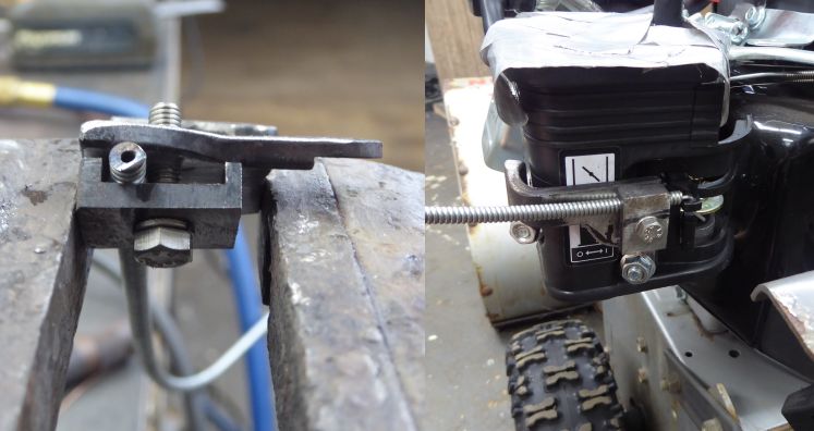
And as a bonus, it all still fit on the engine! The choke cable connects to the lever via a small hole drilled into the plastic. Will it work long term? Who knows if the plastic will survive 10 years of being pulled on by the cable. However as functional as this choke arrangement is I'm not very happy with it. I'll get to that a bit later.
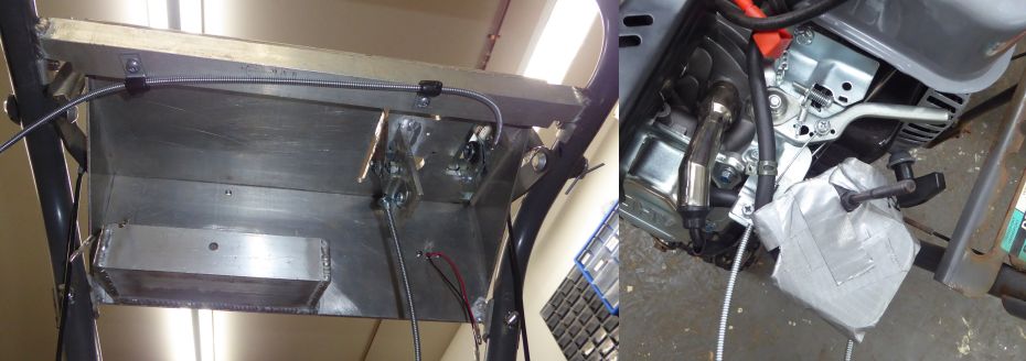
Then the cables were ran from the controls down to the engine. A few cable clamps keep the throttle cable secured as it has to make a very sharp bend from the lever. This is not ideal for the cable as it prefers to be as straight as possible. The throttle lever on the engine provided several different cable mounting options so it was fairly straightforward to attach on the engine side. And the choke cable fit well into the fabricated bracket and after some trimming and bending, into the choke lever (not visible in this picture).
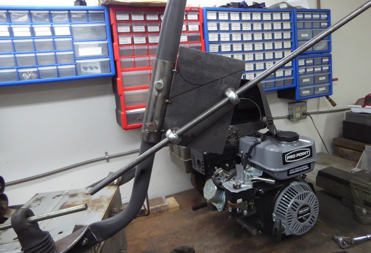
The original HSSK50 is a vertical cylinder design and rather narrow compared to the Pro Point OHV Honda clone with its 45 degree cylinder. This meant that the original chute turning crank wanted to occupy the same space as both the valve cover and carburetor. It clearly needed to be relocated which honestly, is something I have been wanting to do for a while anyway. I had always considered it way too low and hated having to stop and bend down to adjust the discharge direction.
A simple bracket made out of some angle iron relocated the crank rod lower to clear the engine. But wait, I already said that even in stock form it was way too low. We'll get to that a bit later. For now, it just needed to be operational because I wanted to fire this thing up. It took a little bending of the bushing arm at the front in order to keep things moving smoothly. There was plenty of tolerance on the chute to accept the new angle.
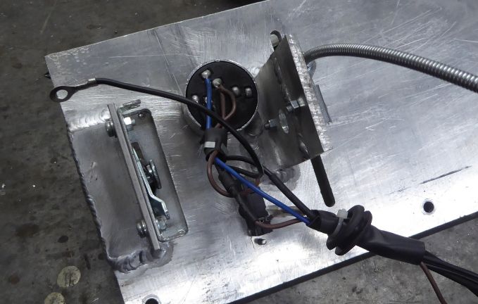
This engine is equipped with not only a 12V electric starter but also a 500mA charging circuit. Which of course means that the snow blower now needs a rudimentary electrical system. Most of the system came with the engine however since the key switch was relocated to the handle from the engine, the wires needed to be extended.
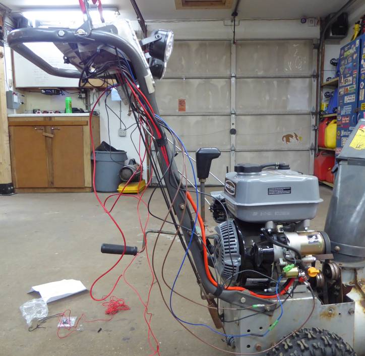
The battery 12V connects to the starter solenoid via a 10 AWG wire, while the battery negative connections to a bolt on the engine to ground the chassis. From the starter solenoid, a small 12V constant wire heads back to the common terminal on the ignition switch through a circuit breaker. The ignition switch IGN (power) line runs back to the engine to connect to the ignition module, and of course the starter/crank signal connects to the coil of the starter solenoid. An acceptable harness came with the fog lights so it was used, connected directly to battery 12V. Parts of it had to be shortened as it was of course designed to run from a dash up to the front of a car. The switch it came with was also highly questionable, so a proper weatherproof toggle was used instead.
A little bit of corrugated wire loom keeps things secure and tidy.
It was finally ready to fire this thing up!
|
|
The first engine startup on a project is always an auspicious occasion. In this case it was almost completely uneventful. I set the choke, then realized I had forgotten to tighten the choke cable bracket, so set the choke by hand. Turned the key and it started surprisingly quickly. After opening the choke and setting the throttle, both the auger and drive wheels worked as expected. Excellent. Now that I know the thing works, let's get back to that chute turning crank.
It has always sucked reaching down to adjust the direction of the discharge chute, and having to move the crank lower to clear the valve cover made it even worse.
I started the relocation by splitting some steel tube having the same diameter as that of the handle. Then drilled two mounting holes to match the existing holes in the handle. Two hymn joints support the steel rod which will extend the crank and a 3MM steel plate brings it all together. You can also see the marks showing where the plate will be trimmed of excess material once everything is finalized.
To lengthen the crank rod, the ends of the new rod and the existing crank were ground to a dull point to allow for weld penetration. To keep things straight, both ends were clamped firmly into piece of aluminium angle.
Half of the joint was welded then left to fully cool. It was then carefully ground flat, the crank re-jigged and the other half welded. All in all it turned out basically straight. Was it perfect? No. There is some slight wobble. But we are not talking about an assembly here which turns 100,000 RPM. Cranking as fast as I can it might turn 120 RPM.
Mounted back on the handle bars, the chute crank is now much closer to the controls and far easier to manipulate while the snow blower is moving. The bracket was also cleaned up a bit after fully welding to remove the excess material and sharp edges.
Probably for safety reasons Craftsman originally limited the chute rotation to about 160 degrees. Which I guess makes sense as they likely didn't want lawsuits from those who would turn the discharge chute towards their face, take a thrown ice chunk to the eye, and obviously blame Craftsman. I however have enough common sense to not turn something throwing objects towards my face, and would much prefer a bit more chute rotation.
With some quick grinder work, an additional notch was added to each side of the chute turret. This has the effect of creating another gear tooth for the crank to engage, thus extending the rotation range. The end stops on each side had to be modified so the stop was cut off the plate, moved inwards about half an inch, and welded in place.
The end result is as desired; about 200 degrees of movement out of the chute meaning that I can direct discharged snow about 10 degrees behind me at each end of the rotation. Very handy!
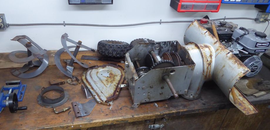
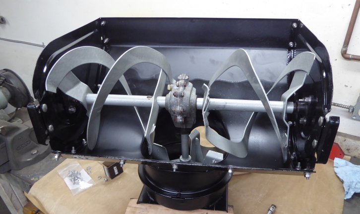
After all that work fabricating and upgrading, there was no way I was going to leave the thing looking worn out and rusty. The inside of the impeller housing had no original paint left so would create rust puddles as the packed in snow melted. The auger housing was in similar condition. Over the years of service, a fair bit of the hardware had also been replaced by basically whatever was on hand so it was a mixture of both metric and SAE.
I disassembled everything as much was practical. When painting something, it's a tradeoff between the quality of the job and the amount of work one is willing to put into the prep. Could have taken the thing completely down to individual components however the benefit vs. work graph starts to trend very much more towards work past a point.
If you look closely within the gear case you can see that I replaced the friction disk. The old one was worn out, oh, about 10 years ago. Also the impeller bearing was well past its prime so that was swapped with a new sealed variant
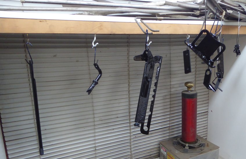
The blast cabinet made quick work of the small parts. Actually, not as quick as I would have thought as it seems some of these (for example, the transmission selector gate) are powder coated. Being slightly rubbery, powder coating takes some effort to blast off. Once cleaned up, it was 3 coats of POR-15 in either black or silver.
Dealing with the auger/impeller housing was definitely less straightforward as it only fit in the blast cabinet by about 90%. Which meant having to seal off the open side of the cabinet with plastic vapour barrier, and some seriously awkward manipulation of the blast nozzle while constantly repositioning the part in the cabinet. It was not fun. I've blasted some items too large for the cabinet before but I'd have to say, this was the most unpleasant. Ultimately it was a good decision to blast as the rust level in the impeller housing was impressive. There would have been no way clean the rust out of the pits otherwise.
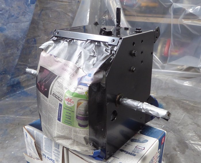
Thankfully the transmission housing wasn't nearly as bad, so I was able to strip it fairly quickly using a knotted wire wheel mounted to an angle grinder. It would have seriously sucked having to mask it all off for blasting.
I chose to key off of the black and grey engine colour scheme and continue that throughout the whole machine. The mechanical parts received a base coat of black POR-15, then depending on the final colour either two more coats of black or silver.
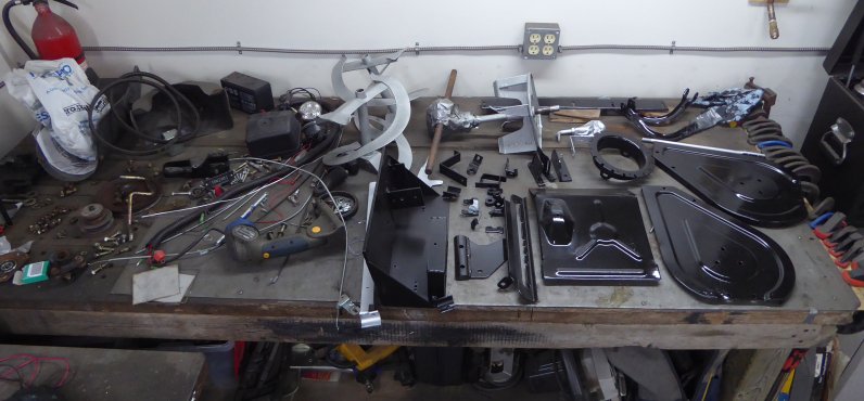
User controls, brackets, the handle and a few other items that are subjected to less abuse were top coated with POR-15 engine enamel. Mainly because I ran out of silver POR-15 in the middle of the job and didn't want to stop and wait for more to arrive.
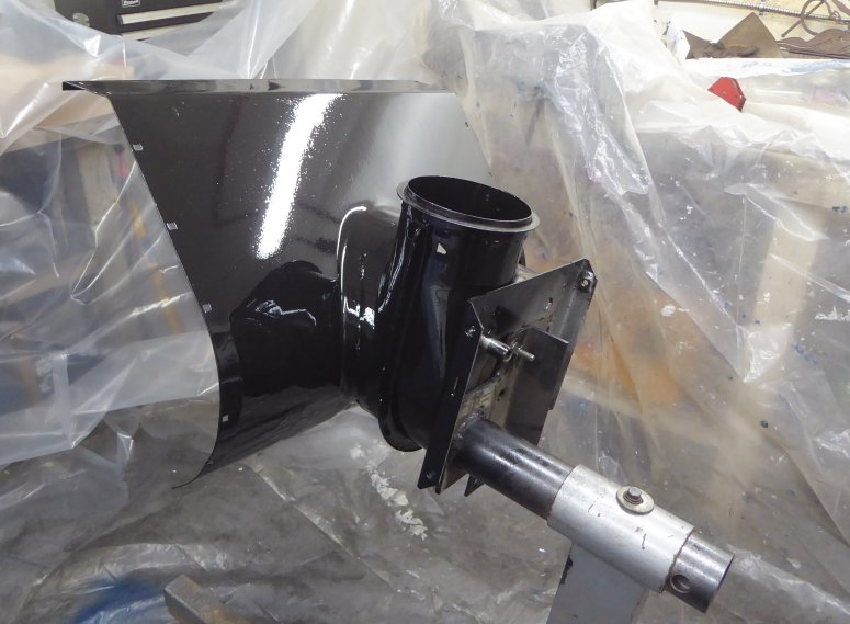
The paint was dry, so final assembly could take place. And as they say, installation is reverse of the removal. During reassembly of the impeller section I replaced the impeller bearing. The old one was long past failed as the seals had worn out years ago, allowing the lubricant to vacate and the bearing to rust accordingly.
During final assembly hardware was replaced with stainless equivalents whenever possible. All hardware was installed with anti-seize. Additionally, everything was lubricated with synthetic grease. The main drive chain was thoroughly cleaned with solvent then soaked in chain lube.
Everything fit as it should primary because I had it on and off so many times during mockup. The original plan was to 3D print some brackets to hold the control cables however during assembly I became less happy with the cable arrangement. I'll get to the details a little later. For now though, it meant just using some cable ties which is quite likely what the OEM would have used anyway. Or at least some springy metal clips which would have rusted in a year or two.
With the battery installed, the final wiring was done underneath the console. Well, not quite the final wiring as changes are planned in the future, but final for now. A few additional clamps secure the control cables. Sadly this puts the throttle lever into a bit of a bind as these stiff control cables aren't designed to make such tight bends. One of the issues which will need to be sorted later. The lever still works however doesn't have a lot of travel due to the lack of movement of the corresponding throttle lever on the engine, and is rather stiff.
As I mentioned earlier, the chute turner crank no longer made a straight run to the turret. What I thought would be a simple fix with a u-joint turned out to be far more hassle that I had assumed. It seems that small u-joints are not as plentiful as I had speculated, and when available, have pricing bordering on outrageous. I was just flat out unwilling to pay $50+ for a small u-joint that I would still have to improvise a boot for.
Any mechanical u-joint is going to be a maintenance item as well requiring at least yearly greasing. After wandering around my shop for a while checking junk...er, I mean "assorted parts" bins, the solution was found in my box of spare Vintage Air parts in the form of some 3/8" A/C high side hose. This stuff is about 1/4" thick, with a stiff rubber core surrounded by cloth belts. Yet has enough give to flex at a tight radius without collapsing. With a bit of smoothing on the shaft, plenty of lubrication and copious swearing I was able to convince the hose into place. The result is a smooth turning u-joint, completely maintenance free.
And that, as they say, was that.
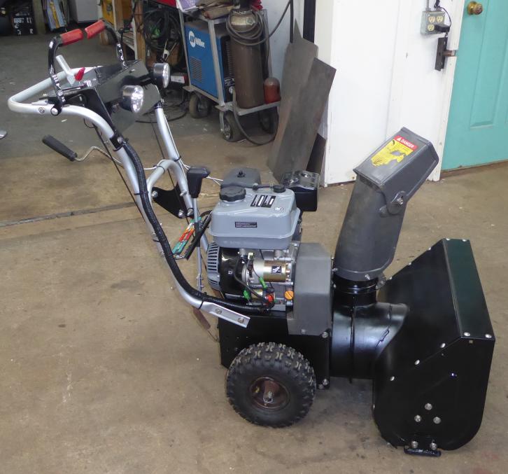
Adding the u-joint for the chute turner was the final assembly step. Now if you look closely, you will see that the wheels were not blasted and painted. Because the right side rim is rather bent, I figured I'd wait until I could locate a set of replacement rims before bothering.
Once assembled, everything worked as expected. Once of the benefits of fully assembling in mockup first before making everything pretty for final assembly. At this point it was a matter of waiting for some snow.
The winter of 2018 was kind of disappointing. An unusually high snowfall amount was predicted yet sadly, did not really materialize. Damn global warming. A far cry from the first season I had this thing which saw 36" of snow in one weekend, I think total snowfall for 2018 in my area was about 36". Which meant all that extra horsepower was wasted. Regardless, I am happy to report that the snow blower performed nearly flawlessly. I did not experience any issues with the engine starting and running in cold weather. The electric starter was a great convenience and anyone using a snow blower after dark without a set of bright LED headlights is a crazy person.
We did have a few warm days followed by some snowfalls which resulted in big piles of slush which previously would bog the machine down, typically clogging it. Now I must say there is something strangely satisfying about seeing a massive fan of mostly slush blasting from the chute while the engine barely registers the load.
With luck, 2019 will be a major snow dumping so the blower can get a proper shakedown workout.
As I alluded to earlier both the throttle and choke levers presented some difficulty. Well, not so much the levers but the cables. These styles of actuator cable are not designed to make tight bends, unlike a more flexible version such as bicycle brake cable. The result is that the throttle lever is very stiff, and that the choke lever has the tendency to just bend the cable instead of pushing it into the sheath. The travel of the throttle lever also leaves a lot to be desired with only about 1/4 of its range being usable. I'm currently considering two solutions.
Upon using the snow blower I also discovered something: it seems the balance of the machine is set very carefully at the factory. They balance the snow blower on the wheels just right for enough pressure on the front of the unit to keep it planted firmly on the ground, yet with enough reward weight so the front can be lifted easily. The additional weight rearward of the wheels, in the form of all the stuff I mounted to the handle (including a heavy battery) has made the blower somewhat rear heavy. If parked on a slight rear incline, it will want to tip over. I don't see an elegant solution to this as I still plan to add more weight to the handle, so I think the only remedy is going to be a bit of weight added to the front. At some point I will bolt a heavy steel or lead plate underneath the lip at the front of the auger housing.
Please read the following FAQ before emailing me about this project. It may answer your question. The FAQ is updated based on common questions I receive via email.