| Home > RX-7 > My RX-7 > Project Tina > Project Tina, 2009: Boost Controller, Fuel Tank Fab, Transmission Destruction, TII Transmission |
| Home > RX-7 > My RX-7 > Project Tina > Project Tina, 2009: Boost Controller, Fuel Tank Fab, Transmission Destruction, TII Transmission |
It's been more then a year since I posted the last update on my ongoing project. There has been such a lag in threads mainly because it is almost done. I've just been driving the car and enjoying it. But there is still a little work to do not only involving further modifications, but also to replace some weak links as well. This update primarily deals with two tasks; installing a boost controller and fabricating a new 100 litre fuel tank. Near the end, I also start prepping the car for a TII transmission swap.
We begin where we left off last year; the installation of the rear strut bar. As detailed in the last thread, the strut bar was fabricated from 6061 aluminum as a first project after purchasing a TIG welder.
Since I installed the GT40R in 2007, I had been running on the 0.9 bar wastegate spring. Consequently the car made 13 PSI almost exactly. Even though the turbo is falling asleep at this pressure, the car managed to put down 392 RWHP on the dyno. A little more tuning after that to smooth out the top end and midrange of the map put the car at around 420 RWHP (measured on my calibrated butt dyno). Not too shabby at all, but a little more boost was needed to wake up the turbo and also eliminate some lag as the wastegate started to crack open before full boost was reached. I chose the HKS EVC 6 boost controller because it is a closed loop electronic boost controller with a load of useful features. Of course, what I mostly wanted was an electronic "dial a boost" that would simply make the pressure I set it too without a lot of tweaking or manually editing solenoid duty cycles. As the ECV 6 has two boost settings (well, technically 3 if you count scramble boost) I planned to have the low boost set at 14 PSI, and then the high boost set at whatever results in 500 RWHP.
Before all the fun though, the controller must be installed. My existing wastegate line is braided stainless with AN fittings, so I needed to adapt the lame nipples HKS put on the solenoid (really a stepper motor) to NPT fittings or AN flares. Seriously HKS, this is a $600+ boost controller, is it too much to ask for NPT ports instead of plastic nipples? As it turns out, a friend had come back from the hydraulic store with some Push-Lock -4 hose barbs which fit the HKS supplied hose perfectly, so I grabbed two and mocked up the assembly.
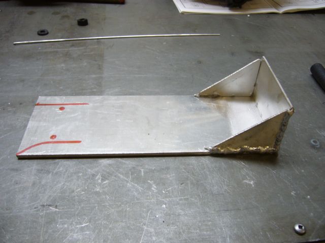
A bracket was needed to mount the solenoid assembly to the car, so I began fabricating one out of some 1/16" aluminum sheet.
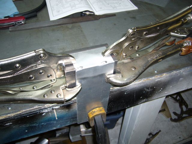
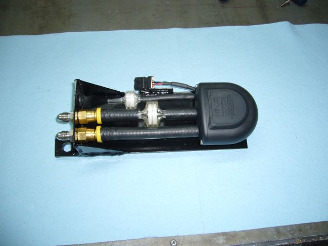
Here is the bracket fully welded with the solenoid mounting position and holes marked.
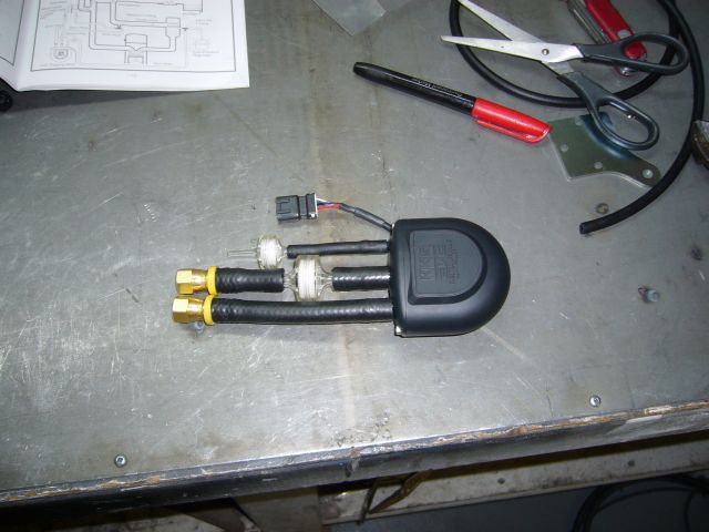
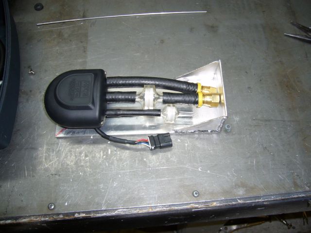
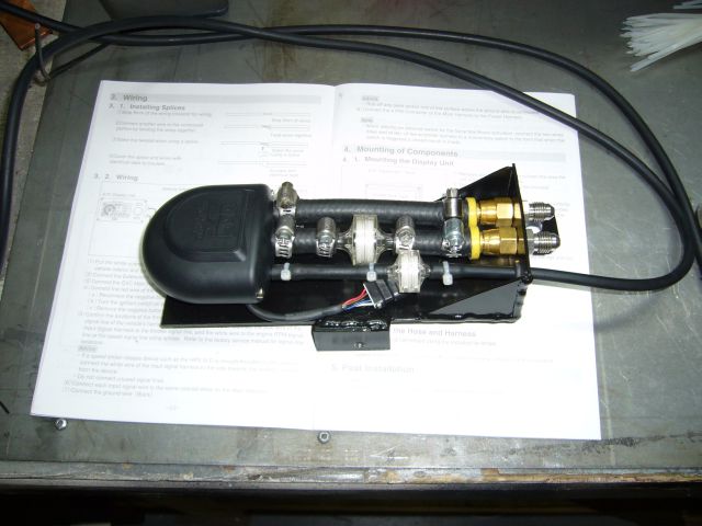
After bolting the solenoid to the bracket I mocked up the hoses so that I would know where to drill the holes for the remaining fittings. The idea is to make this its own little module that just bolts up to the car somewhere out of harms way. Boost solenoids are sensitive to heat and should be kept well away from the turbo and exhaust.
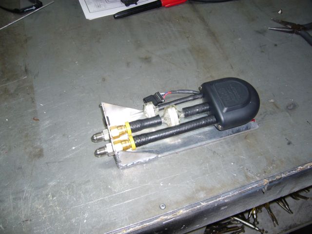
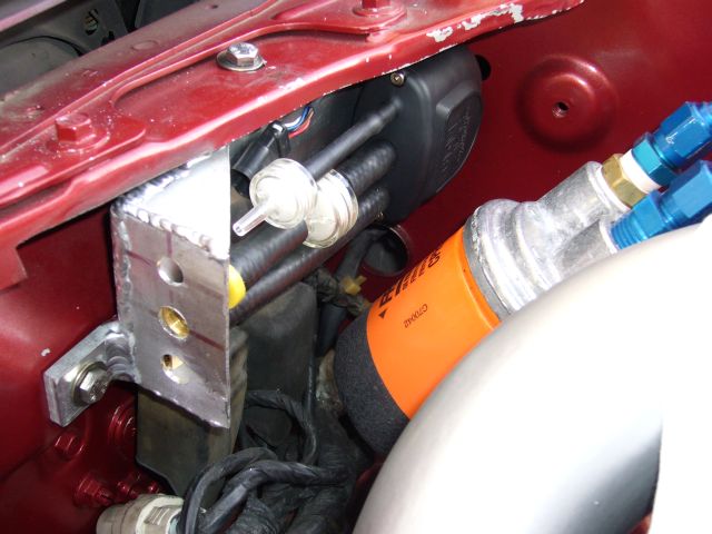
Once the holes were drilled I screwed some -4 male on male fittings into the Push-Lock barbs. This locked the hoses to the vertical section of the bracket as there was just enough space between the -4 fitting and barbs for the sheet aluminum to fit. I also installed a small rubber grommet in the remaining hole to protect the controllers vacuum line.
I ended up having to trim the radiator/headlight crossmember a little to fit the solenoid assembly where I wanted it to go, but aside from that it was a simple matter of welding on two 1/4" tabs to allow it to be bolted to existing holes on the car.
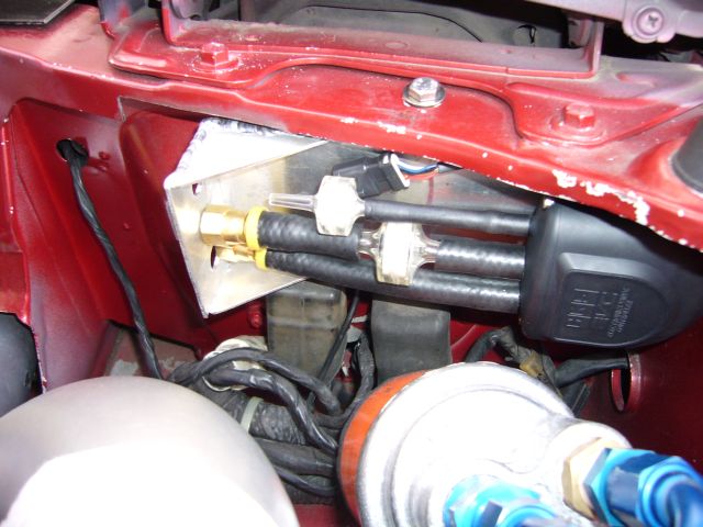
Another view shows how the solenoid assembly tucks under the rad support for protection and to minimize the useful space it takes up.
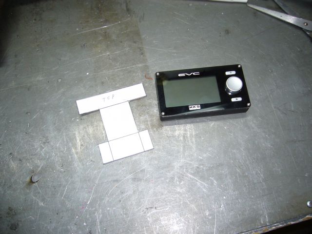
I pulled the solenoid bracket apart for painting and while alternating paint coats, started making a bracket to support the controller itself. I didn't want it stuck to the dash because I planned to set-and-forget the controller and didn't always want it in my field of view. So I decided to mount it to the interior of the glove box door on a small bracket. The first step in creating this bracket was to make a paper template.
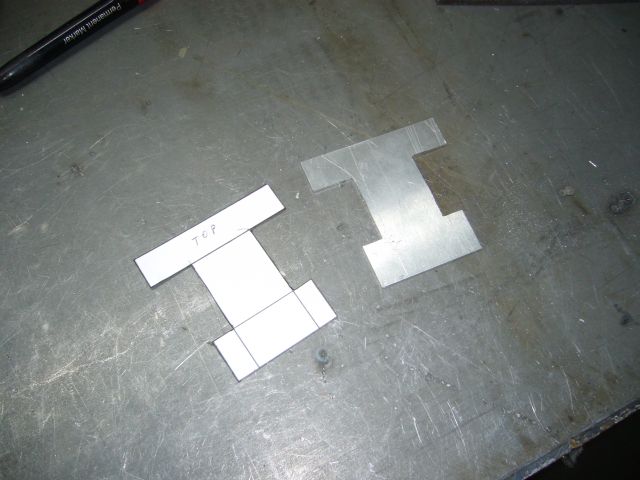
Then I cut the bracket out on the band saw and finished the edges manually with a file.
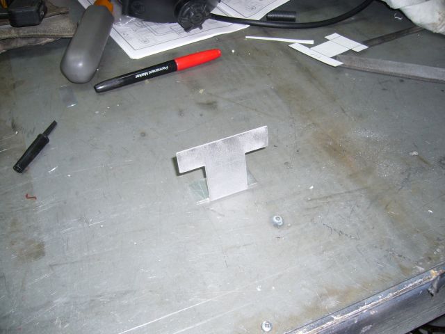
The bracket was then finished off with a slight bend in the sheet metal brake. This is so that when the glove box door was opened, the controller would face the driver.
By then the paint on the solenoid bracket was dry so final assembly on that part took place.
I then mounted the bracket for the display to the inside of the glove box door. This necessitated disassembling the door to access the other side of the black plastic backing. Two machine screws and wide washers were used to secure the mounting bracket. At the same time, I began running the wires for the controller. The controller requires a standard power and ground connection which I just supplied via an extra fuse on my aux fuse panels. Additionally it wants an RPM input (took that from the tach input at the instrument cluster) and a TPS input (I tapped into the TPS signal line at the Microtech harness). The line out into the engine bay for the solenoid exits through the harness grommet and follows along the frame rail to the front of the car.
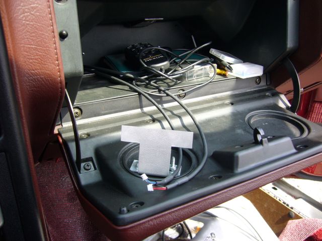
Oops, I almost forgot this picture which shows how the vacuum line for the controller passes through the grommet. You can also see that I clamped all the hoses for good measure. I had originally intended to use crimps to secure them, but realized that I might have to replace those little plastic filters some day so I settled for lame worm gear hose clamps.
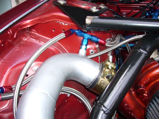
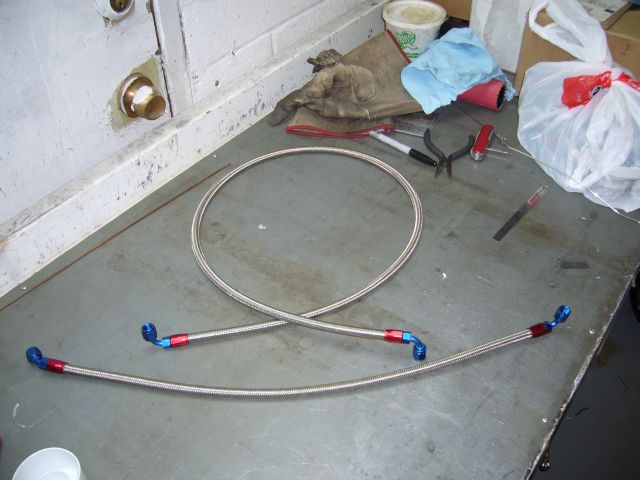
Because it really sucks when wastegate control lines blow off under boost, I had already used braided stainless line with AN fittings to connect the wastegate to a boost source. Since there were a few more lines to run for the boost controller, I assembled them with -4 braided stainless to match what was already used. I've said it before and I'll say it again: working with -4 braided stainless line sucks! The tips of my fingers were shredded afterwards but I was able to assemble these with a minimum of swearing.
The controller needs a supply of pressurized air so I just added a T fitting to the boost source currently used for the wastegate. This required changing the fitting on the line feeding the wastegate from a 90 degree to a straight end.
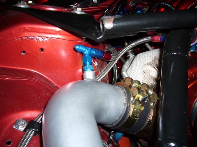
Then it was just a matter of connecting the lines up. First, the connection to the boost source was made.