| Home > RX-7 > My RX-7 > Project Tina > Project Tina, July 15th, 2004: Painting The Engine Bay, Porting The Engine, Shaving Lower Intake Manifold |
| Home > RX-7 > My RX-7 > Project Tina > Project Tina, July 15th, 2004: Painting The Engine Bay, Porting The Engine, Shaving Lower Intake Manifold |
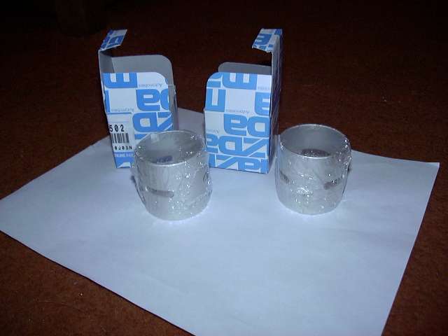
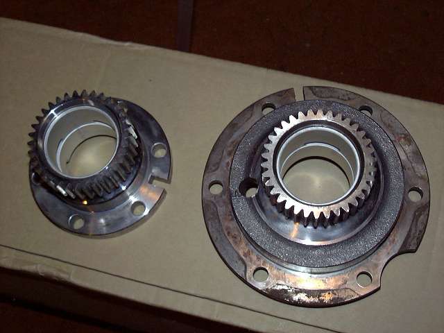
It was about that time that my apex seals and 3 window bearings arrived from Atkins. I chose the Atkins 2 piece 2MM seal, and had them throw in a set of Mazda 3 window main bearings. The bearings are shown below. The stock bearing has one oil hole that is fed by oil passage in the stationary gear. These holes sit at the top of the bearing, and are the eccentric shaft's only source of oil. So in a stock engine, the stationary bearings, rotor bearings, eccentric shaft and eccentric oil jets are lubricated by oil from an opening in the bearing about as thick as a pencil. The three window bearings each have three oil passages, hence the name. This assures a much better flow of oil to the eccentric and associated parts. However, installation requires modification of the stationary gears, which I will explain later on. Sorry, but no pictures of the apex seals. We've all seen apex seals, right?
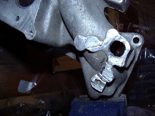
So back to the intake. The 6 port actuator supports and rod bushing area was cut off. The 6 port actuators are not needed in a turbo application, and frankly, they won't physically fit.
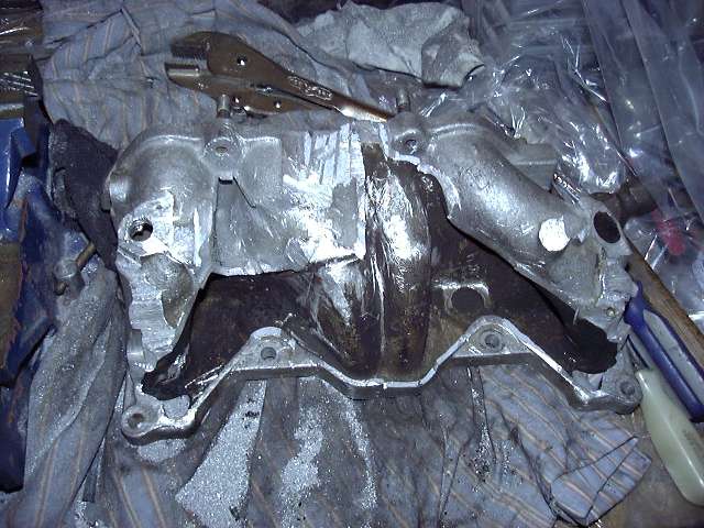
Beginning to remove the emissions passages on the lower half of the intake. You can see the empty space starting to show.
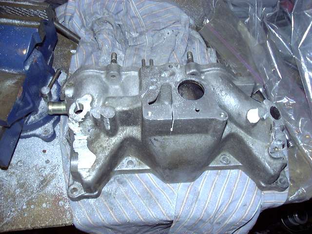
Removing the ACV mount.
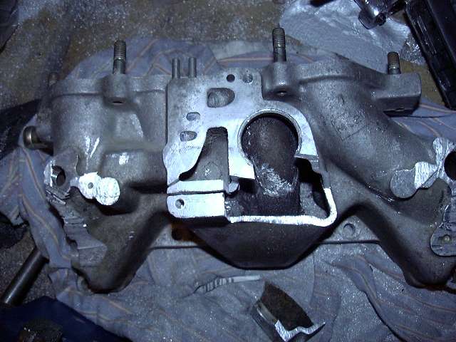
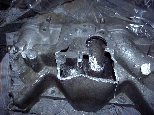
Now here is the NA lower intake with all the emissions passages removed. You can see the massive amount of empty space inside the casting. What did strike me was how well the whole thing was designed. See, the air from the air pump flows through the ACV, and into either the cat (during 5th gear cruise), into the exhaust ports (during regular driving) or into the rear rotor (during decel). In order to get into the exhaust ports, the air must flow over all the lower intake runners. I am sure that this has a major cooling effect on the air being taken in by the engine. Whether this makes a difference in "off the line", I can't say. But seeing the inner workings of the manifold is pretty cool. The final manifold will have all the rough edges taken off and be painted to match the rest of the engine. Also, the holes have since been TIG welded shut, but I don't have pictures of that (yet).
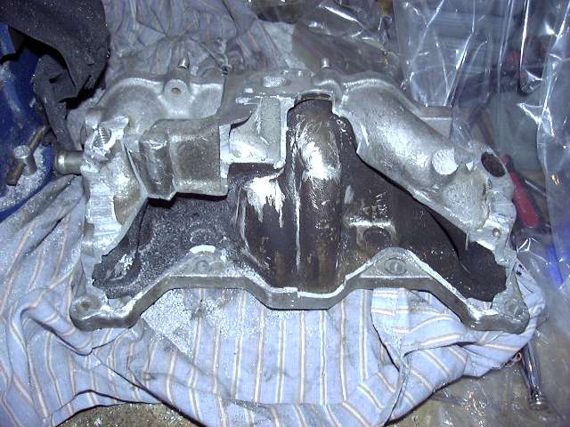
Another picture of the intake.
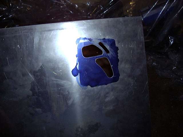
OK, lets get back to the serious work. Here's the intake port template with the "eyebrow" cut out. It's a fairly poor picture, and the port looks much better in person. The port was drilled out, then ported using a Dremel tool and a spiral cutting bit. The bridgeports are much too small to do with the big die grinder.
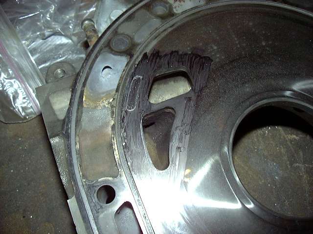
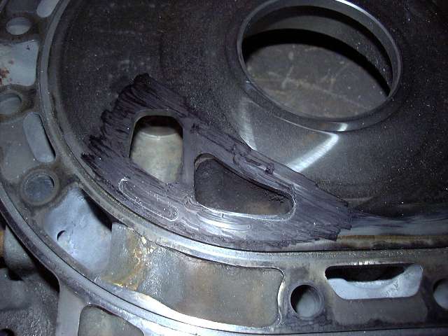
These two pictures show the ports scribed onto the housing. Note the aux (the "5th and 6th ports") are being left untouched. The secondary port is only being moved towards the outside a little.
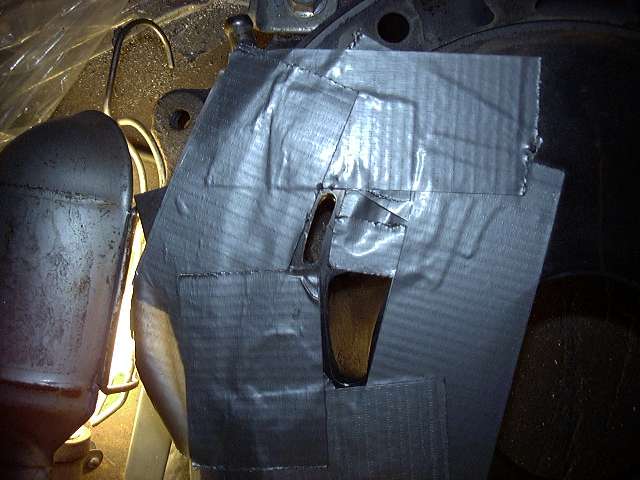
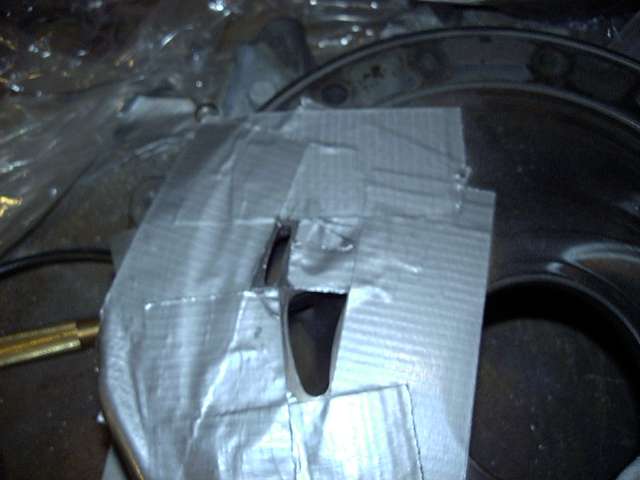
Very important to mask everything off before porting. That's about 4 layers of duct tape.
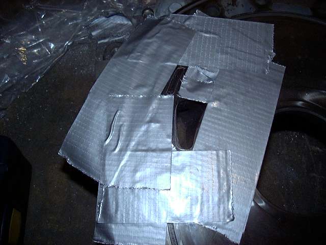
To start a bridgeport, you first drill out the rough shape with a 3/16th drill bit. I started with one size smaller, center punching first. I then enlarged the hole.
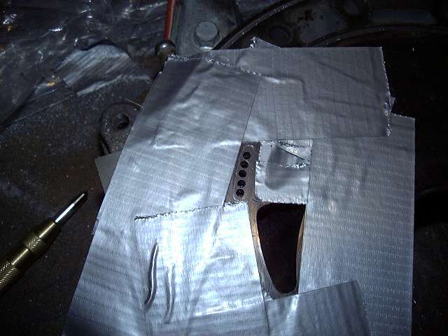
The "eyebrow" was created using a Dremel tool and very thin grinding stone. It took some time, but also made it very difficult to screw up. That's the thing about the die grinder: it will just eat through anything. There is no forgiveness. However, the Dremel works slowly and requires you to take breaks. However, it is more difficult to get a uniform cut with the Dremel because the bits are so small.
Here's the end result of the bridge and the secondary ported.
And is the scribe on the opposite iron.
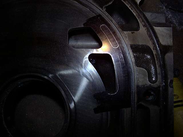
And the port is finished.
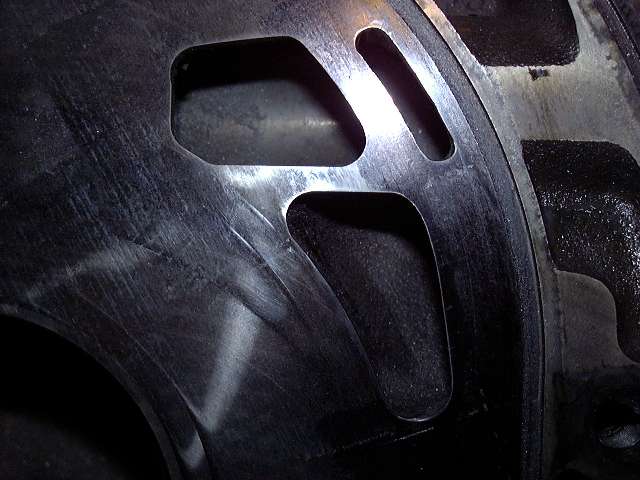
At this point, the major modifications are done. Now it's time to clean. And clean. And clean, and clean, and clean. Then some cleaning took place, after which there was cleaning. Following that, I cleaned. OK, you get the point. In order to get the finish I wanted on the rotor housings, they were given a quick and dirty polish. Ahhhh, shiny...
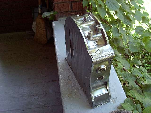
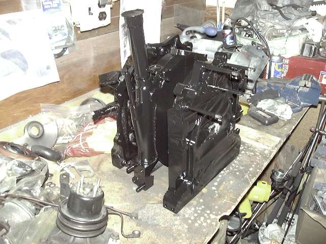
While I was dealing with the housings, I also masked and painted the irons. They were masked off with duct tape (Note: if you do this, use masking tape. Much easier and cleaner to remove) and painted with VHT gloss black. It's a brake caliper enamel that is good to about 600 degrees or so. Also very chemical resistant. It worked so well on Tony's engine that I decided to also use it on mine.
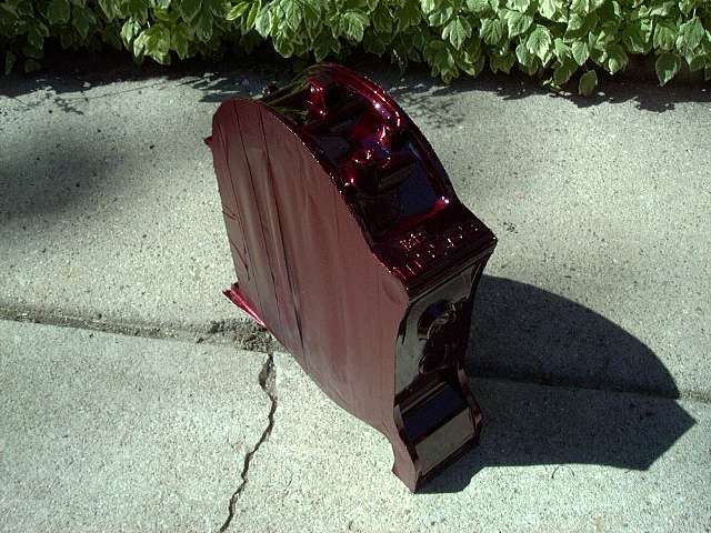
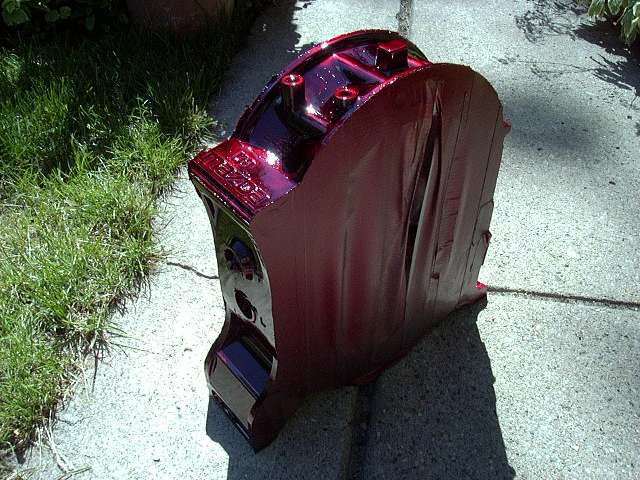
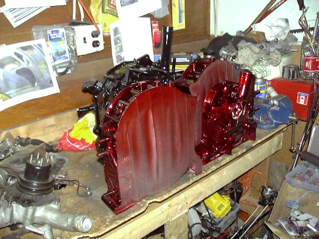
Each rotor housing was given 4 coats of Dupont's MetalCast in red. I must say that the result was bloody brilliant. The housings took on a life of their own. You can see every detail of the metal through the candy coating, and in sunlight it's just like looking into a pool of blood. Very cool. The "Mazda" logos will be highlighted in black.
So here are the stationary gears with installed three window bearings. Installation is simple, but requires some machine work. First, the old bearing is pressed out. In order for each window of the new bearings to receive oil, a channel must be cut on the inner side of the stationary gear. This channel is about 5-8MM wide (exact dimensions are unimportant), 1.5MM deep (don't go to deep otherwise you weaken the gear) and in line with the oil feed hole. When the bearing is pressed in, the windows roughly line up with the channel, thus feeding the windows with pressurized oil. I don't doubt that someone somewhere has made this channel with a Dremel tool, but really, it needs to be done on a lathe. I just sent my gears to a local machine shop. The entire operation cost $40. The new bearings were then pressed in.
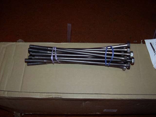
Oh yeah, all the other engine parts need to be spotless as well. Tension bolts, counterweight, eccentric, stationary gears, chain, oil pump, sprockets, spacer assembly, etc., etc. Shown here are the cleaned up tension bolts. Amazing what a wire brush can do to 18 year old bolts.
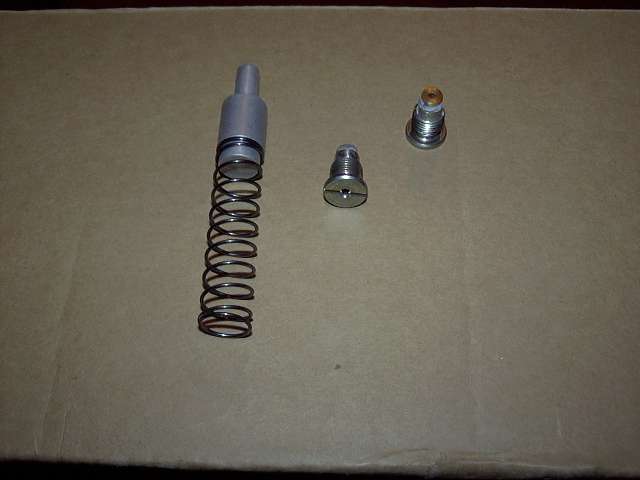
The thermal pellet and modded eccentric oil jets. The thermal pellet eliminates the stock thermostat at the front of the eccentric, assuring a constant supply of oil to the eccentric oil jets. These jets have been modified. A #200 Weber air jet has been installed in place of the stock check ball assembly. The result is increased cooling spray to the inside of the rotors at the sacrifice of some low RPM oil pressure. It's a tradeoff that I willing to accept.
Finally, all the engine parts painted up and ready to go.
So that's it. The engine is now ready to be assembled, which will take place this weekend. I'm fairly excited, seeing as how this has been 2 years in the making. The engine will be assembled in my basement, then the short block brought up to the garage where the accessories will be installed. Then it will be dropped into the car. I still need to get my flywheel resurfaced and pick up a clutch before that though. And the lower intake needs to be finished (it has to go on before the turbo). But regardless, the project is FINALLY starting to come together. I am really hoping to fire her up before the snow flies.