| Home > RX-7 > My RX-7 > Project Tina > Project Tina, August 7th, 2006: Fuel System, Intake Manifold Installation, Exhaust Fabrication |
| Home > RX-7 > My RX-7 > Project Tina > Project Tina, August 7th, 2006: Fuel System, Intake Manifold Installation, Exhaust Fabrication |
It's been a long winter and much has been accomplished since the last update. It's getting close to the point where the car will start for the first time in 3.5 years and for the most part the hard work is done. At this point, it's mainly assembly work with some light fabrication.
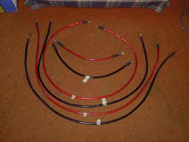
We last left off with the fabrication of the main battery and power cables. This was after the construction of an upper intake manifold from scratch, so it was a nice change to do something simple.
During the winter, working in the garage is less then pleasant so I tried to get as much work done inside as I could. The first little task was to make a blow off valve flange. The flange was made using 4MM thick steel. To get the pattern for the bottom of the Apex'I BOV, I scanned it into the computer and then cranked the contrast up. The resulting printout is a template that can be used to make the flange. Holes were drilled and tapped for M5 Allen head bolts.
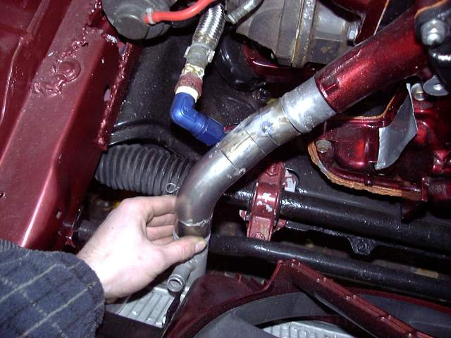
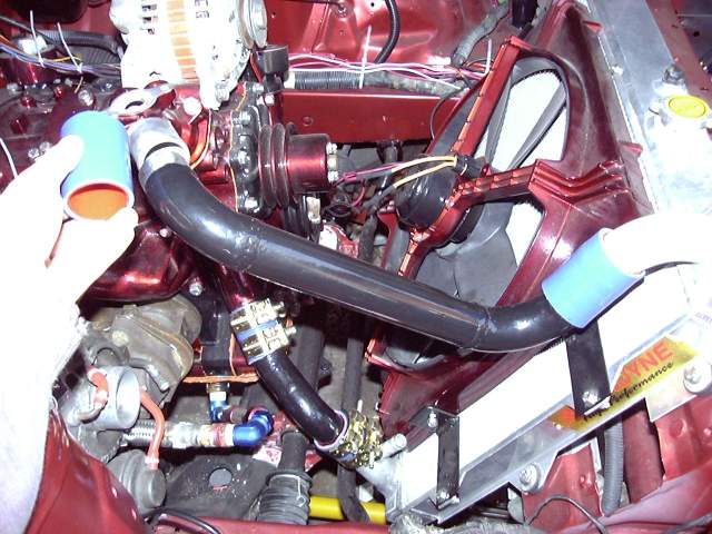
There were a few days above zero degrees so I took the opportunity to fab up the lower rad pipe. Working with pipe is fairly simple once you get the hang of visualizing the angles in your head. I like to work starting from each side and then meeting in the middle for short runs, but for longer runs you need to work from one side to the other. The tubing is 1.5" OD, with stainless weld els used to make the bends. I wanted to keep this pipe as low profile as possible to not interfere with future intercooler piping or the TID.
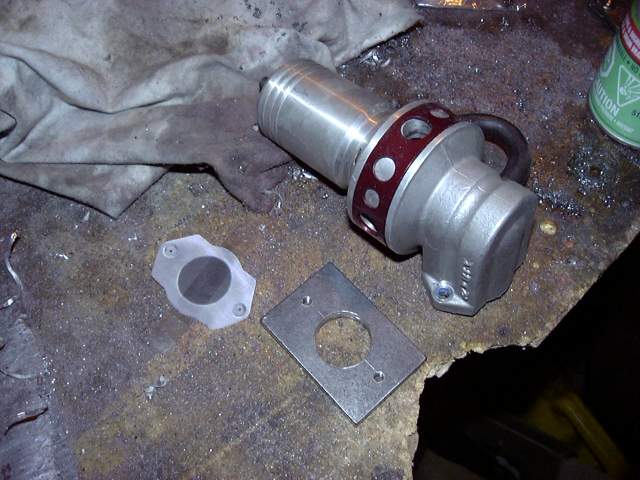
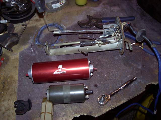
About this time, the parts for my fuel system started to come in. This is the Aeromotive A1000 pump compared to the FD pump I used previously. There's a slight difference in size so I was trying to figure out how I could mount it onto the stock tank flange. After thinking about it for a while, I gave up on that idea and decided to make a new flange.
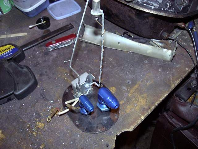
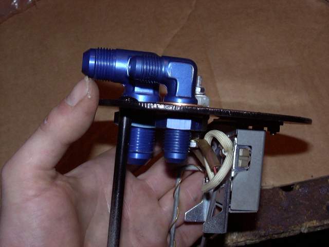
The new flange was made by tracing the outline of the gasket onto a sheet of 12 gauge steel, and then cutting that shape out with a jigsaw. Some minor grinding on the edges finished it off and the screw holes were drilled. To feed fuel in and out of the tank I used -8 (for feed) and -6 (for return) AN bulkhead fittings. Part of the reason it was impossible to use the original stock flange was due to the size of these fittings. The picture below shows the internal tank parts being checked for fit.
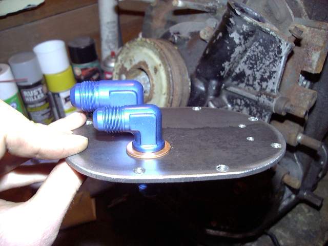
Once the positions of the fittings were known, holes were drilled and the bulkheads test fitted. Copper crush washers were used to seal things up.
The 12A in the background is a peripheral ported engine that was going to go into my GSL-SE. Since then I've decided to PP the original SE engine to make the swap marginally easier. In case you were wondering...
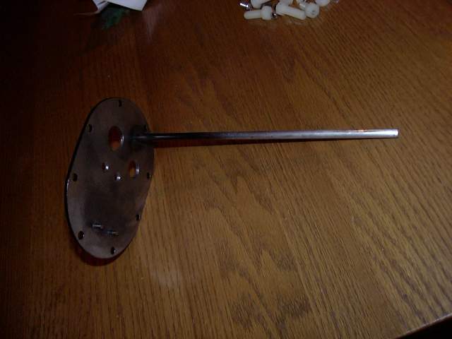
Here's the fuel tank flange all painted up, with the filter support rod welded in place.
The only real issue I had with this whole adventure is figuring out a way to get the two wires for the fuel sender into the tank. I looked at various things others had done but none seemed to be ideal. It's common to just silicone the wires in place, but that would not do. Wire glands are also used, though that means that it is possible for fuel to eventually wick up inside the wire. So I went to every electrical supplier I know of to try and find small sealed bulkhead connectors but fell up short. I managed to find a picture of what I was looking for, but never the actual item.
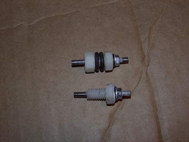
The only option left was to build my own. From the local fastener supplier I picked up some M8 nylon bolts and nuts, some M4 rod and nuts, and assorted o-rings. After drilling a hole through the center of the nylon bolt, it was tapped for M4 and the rod was threaded through it. The top was sealed with an o-ring, as was the bottom (not shown in the picture). Originally I tried to seal the bolt to the flange with the o-rings shown in the picture but that did not work out as they kept squeezing out from between the flange and bolt. So I switched to Dowty seals from the local hydraulic shop. A Dowty seal is basically a rubber o-ring encapsulated in a metal outer ring. The same type of seal is used to seal the tension bolt heads on the engine.
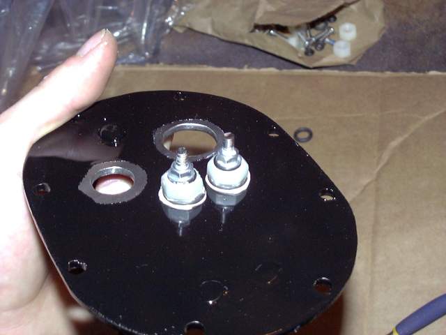
Here's what they look like installed with the o-rings.
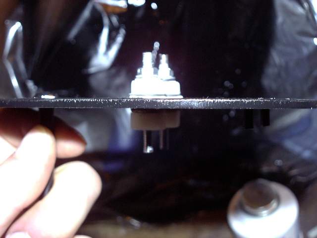
And from the bottom.
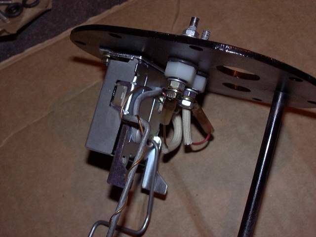
The fuel level sender was then installed next. The ring terminals simply bolted onto the threaded rod passing through the nylon bolt. As you can see, Teflon sealing compound was also used. Again, those rubber o-rings were later replaced with Dowty seals. O-rings really need a machined groove to seat in otherwise they just squish out.
After the level sender was in place, the fuel bulkhead fittings were installed. Copper crush washers sealed them to the flange. These are aluminum bulkheads but steel bulkheads are also available which could have been welded directly to the flange. I chose not to do that since that application really calls for a TIG welder which I don't have. MIG/flux core would just make a mess of it.
Since there was no hope of installing the large Aeromotive pump in place of the stocker, I chose to mount the pre-filter in it's place. The filter has a -10 ORB input, and a -10 ORB output. The input is left to suck fuel from the tank while a -10 ORB to -8 to flare adapter is installed on the output, and a female to female -8 adapter connects the filter to the bulkhead.
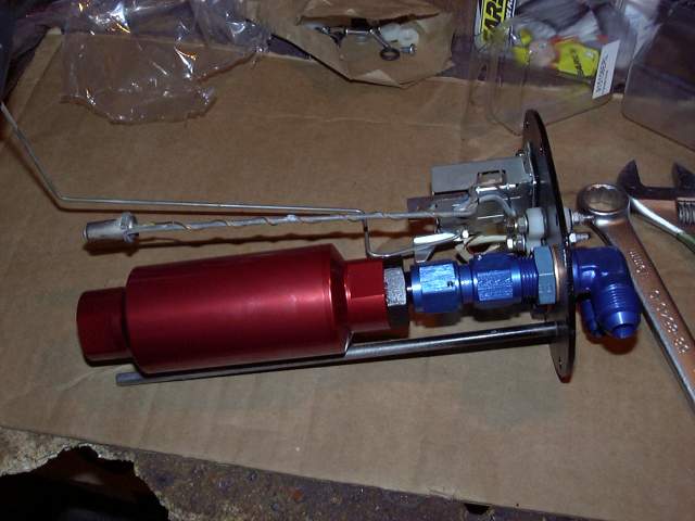
A short length of -6 braided stainless hose connects to the -6 bulkhead as a fuel return. The only worm gear style hose clamp on the entire car can be found here, holding the filter to the tank flange. A little bit of rubber fuel line hose keeps the filter from rubbing.
Since the old metering oil lines were cracked and leaking, I needed new ones. A trip to the local hydraulic store scored some nylon tubing. Here you can see the lines being mocked up. I ran into a slight problem on final assembly though; the 4MM nylon line didn't fit the stock banjo fittings! So I had to go back and order some 4.5MM tubing.
While waiting for the tubing I got a start on the other plumbing. First task was to install the radiator pipes. Short lengths of 1.5" silicone hose (this stuff is expensive!) was used as couplers to connect the pipe to the radiator and engine nipples. The clamps are cadmium plated T-bar style. Unlike regular hose clamps, the T-bar clamps exert equal force around the entire circumference of the hose, provide a much wider clamping area and don't mangle the hose like the regular clamps. They are only about $4 each so the investment is well worth it. By the time all the clamps were tightened, I could practically lift the front of the car with the rad pipes.
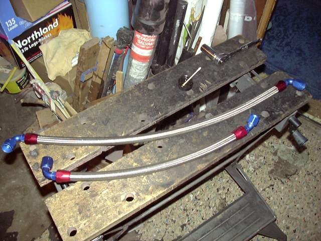
Next on the list was to make up some new oil cooler lines. The previous lines that I had a hydraulic shop make years ago were starting to show their age and the fittings were long past worn out with all kinds of kinks and dents in the tubing. These new lines are made of -10 braided stainless with the appropriate AN fittings. The construction of these lines is covered in the Archives, with a complete parts list.
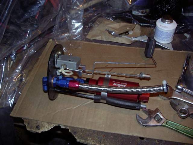
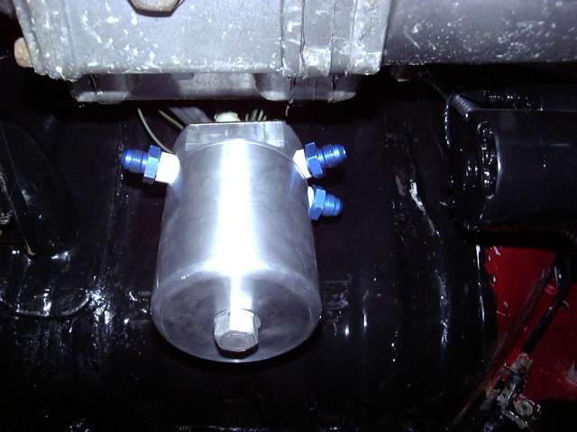
For a fuel filter, I chose the Mallory "competition" canister filter. It's a 10 micron filter with a replaceable element, all in a billet aluminum case. The filter has 2 inputs and two outputs, all 3/8" NPT. I only needed one input so the extra was plugged and then 3/8" NPT to -6 AN adapters installed. The single input goes to the fuel pump, and then each output goes to the appropriate fuel rail.
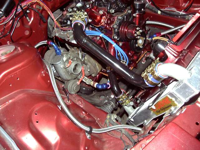
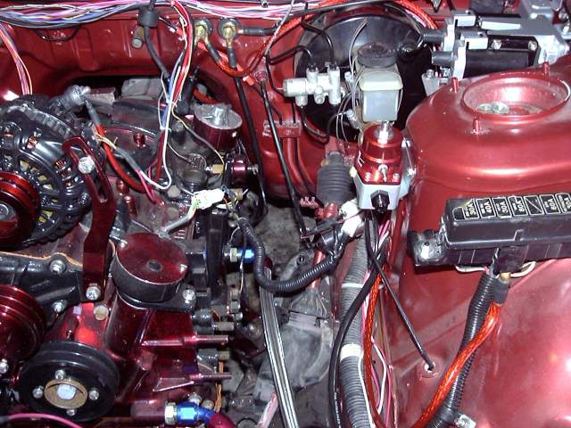
Once the filter was in place it was back into the engine bay to mount the Aeromotive regulator, attach the main power cables to the firewall passthroughs and install the oil cooler lines. The regulator comes with -6 ORB ports for the dual feed and single return, and a 1/8" NPT gauge port. Mounting it on the shock tower was a bit of a pain because the damper is in the way of the inside of the tower. Some creative bending of the fingers was necessary to hold the nuts in place while the bolts were tightened. Aeromotive really needs to revamp their mounting brackets because with the bracket installed on the regulator it is very irritating to get to the bolts, and you can't reach the bolts that secure the bracket to the regulator after the bracket is mounted to the car (got that?).
The main power cables were actually a lot easier to install then I had thought since there was just enough space under the dash to fit a ratchet. A helper (my brother) kept the nuts in the engine bay from spinning. One ground goes to the starter, the other to the drivers frame rail. The positive cables go to the starter and to the main fuse box.
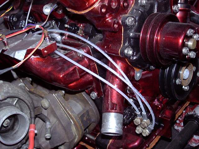
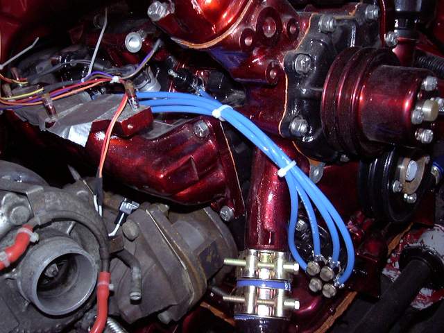
Finally my new metering oil tube arrived so I assembled the lines. A few zip ties keep them tidy. The metering nozzles were all cleaned with carb cleaner and tested as per the factory service manual prior to installation.
Back when I originally did the NA-turbo thing my original oil feed line was made of high pressure fuel injection hose. While it did work, I was always concerned with it blowing and it was a pain to keep it from leaking at the nipples. This new line is made from -6 braided stainless with AN fittings. I had first tried to make it out of -4 but soon gave up in frustration as -4 line is just much too small to work with (the braid kept unraveling no matter what I tried). Here's where it gets a bit weird. A Russel T3 style drain fitting was bolted to the turbo's inlet flange for an oil feed. This fitting fits the stock turbo oil inlet perfectly, seals with an o-ring and then provides a -10 flare. From there, a -10 AN to -6 AN flare reducer was used to connect to the 90 degree -6 end on the feed line. My oil cooler was originally modified with a 1/4" NPT fitting as a oil take off so a simple 90 degreee elbow and 1/4" NPT to -6AN adapter used to connect to the -6 straight end on the stainless line. Much of this is temporary because the upgraded turbo will require different fittings.