| jp |
3 Channel Spectrum Analyzer |
Wednesday, July 08, 2015 9:09:46 PM |
| I appreciate all of the work that went into this; could I take out the led drivers without messing with the rest of the circuit? Also, what is the value for capacitor18? |
| Daniel |
3 Channel Spectrum Analyzer |
Wednesday, August 14, 2013 11:46:35 PM |
| Hello peoples, I was wandering if this circuit would work well with LM3915 instead of AN6884. I think it would be neat to have 10 LEDs per channel. |
| Foolshatch |
3 Channel Spectrum Analyzer |
Thursday, May 10, 2012 9:52:04 PM |
| Error in my last message-- I did not meant LM3900 but those led drivers.
@Audioguru:
About LM3900, that can be replaced with any quad (or single op-amp). About rare led drivers concern is the same thing -- whichever comparator or opamp will do in this schematic. there are possible to make with widely available components. When replacing OP amps, just pinouts needs to be checked.
And LED Drivers... its easy to convert it for opamps/comparators (in that case couple ref-level resistors needs to be added only).
|
| Foolshatch |
3 Channel Spectrum Analyzer |
Thursday, May 10, 2012 9:45:03 PM |
| Nice. instead of LM3900 can be any cheap quad op-amp or also quad comparator in this schematic (though with some minor modifications in schematic - resistors for ref levels). |
| anonymous |
3 Channel Spectrum Analyzer |
Tuesday, December 20, 2011 10:55:15 PM |
| can i add another 2 channels for this project to make it 5 channels? how to do it? |
| lukas |
3 Channel Spectrum Analyzer |
Tuesday, October 11, 2011 3:12:26 PM |
| can i add one led on each ouput from AN6884 ?
so it will be 2x5 LED in each collum is it posssible ?
thanks |
| anonymous |
3 Channel Spectrum Analyzer |
Sunday, January 30, 2011 7:16:37 PM |
| I found this reading the forum..
FROM: audioguru
Posted - Jan 02 2011 : 10:18:10 PM
If you add more frequency bands then you need to re-calculate the bandwidth of the existing bands to make them narrower. The "multiple feedback bandpass filter" design is in Google but uses a "normal" quad opamp instead of the weird LM3900.
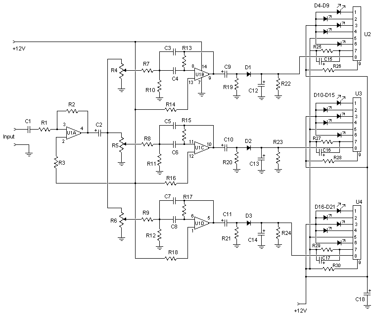
C18 is simply a supply bypass capacitor. Its value depends on how much ripple is on your power supply voltage. If your power supply already has a big filter capacitor or you are using a 12V battery then C18 can be from 10uF to 100uF.
I think the CanaKit is the same circuit.
|
| Aikousha |
C18 is still missing from the parts list |
Monday, January 17, 2011 8:07:24 AM |
| What is the value of C18?
--Thanks |
| Cristian |
3 Channel Spectrum Analyzer |
Thursday, March 04, 2010 7:39:06 PM |
| hey i got two question...im noob at this but, how do you connect audio input to this?????
and what is the value of C18??
i really want to know how to add input though, like an aux cable from an ipod, or something like that. |
| timpati |
3 Channel Spectrum Analyzer |
Sunday, February 15, 2009 11:17:20 PM |
| firstly, thanks for this useful circuit. i saw its schematic but there is not value of the c18. i think it might be between 100-1000 microfarads |
| anonymous |
3 Channel Spectrum Analyzer |
Tuesday, February 19, 2008 7:57:40 AM |
| I will believe it works when I will try |
| implala66 |
3 Channel Spectrum Analyzer |
Thursday, January 17, 2008 6:39:18 AM |
| where can I get a board to make a 10 LED analizer? |
| naimish makwana |
3 Channel Spectrum Analyzer |
Thursday, January 10, 2008 11:08:41 AM |
| very usufull |
| Audioguru |
3 Channel Spectrum Analyzer |
Tuesday, December 04, 2007 6:51:19 PM |
| Good. The errors are fixed.
Nobody said they were fixed.
It is too bad it still uses the obsolete LM3900 quad Norton amp.
The Japanese LED drivers are hard to find. |
| Mike |
3 Channel Spectrum Analyzer / It produces fantastic displays on three LED bars that can be individually adjusted for any particular frequency range |
Sunday, September 23, 2007 12:37:28 AM |
| You said " ...It produces fantastic displays on three LED bars that can be individually adjusted for any particular frequency range "
I would be interested to make it for 16, 31.5, 63, 125, 250, 500, 1000, 2000, 4000, 8000 and 16000 Hz (ref. http://zone.ni.com/devzone/cda/tut/p/id/101 ) by adding 8 more lines but the problem here is to calculate those new values.
My question is could you make one of these and post it here? I am deeply interested. Thank you.
|
| anonymous |
3 Channel Spectrum Analyzer |
Sunday, July 01, 2007 10:55:25 PM |
| i like your analysis but theres a something wrong to your design... |
| Jerry Kohnen |
3 Channel Spectrum Analyzer |
Tuesday, May 08, 2007 10:37:09 PM |
| Your Schematic for this circuit is not correct. You do not have Pin 5 of the Bar Graph IC's grounded in any way, as it should be. Instead you have the output of the center amp stage connected to all of the Pin 5's that SHOULD BE GROUNDED. You have pin 8 ( The Input ) of the center Bar Graph IC grounded, and it should clearly be connected to the output of the center stage amp. You also have Vcc connected to the Bar graph IC thru a resistor, and no current limiting resistor for the LED's, as the LED's are connected directly to Vcc. Vcc should go directly to pin 9, and the resistor's (26,28 & 30) should be used as a current limit for the LED's from Vcc to the LED banks. With the circuit as it is shown, the bar graph part will not work. Without having hooked the amp part up, I do not know if there are mistakes there also or not. Hope this helps those that may be trying to make this circuit work.. (Editor's notes: I'll fix the diagram next time I update the site.) |
| ozkr |
3 Channel Spectrum Analyzer |
Friday, March 16, 2007 12:56:10 AM |
| is there any pcb?
Oscar, Chile |
| David |
3 Channel Spectrum Analyzer |
Thursday, March 01, 2007 9:42:14 PM |
| l like the analysis |
| abel |
3 Channel Spectrum Analyzer |
Thursday, March 01, 2007 3:34:28 AM |
| thank u very much for all this good crt and all the website memeber thank u |