| Home > RX-7 > My RX-7 > Project Tina > Project Tina, August 6th: Fan Controller, Brakes, Suspension and Interior |
| Home > RX-7 > My RX-7 > Project Tina > Project Tina, August 6th: Fan Controller, Brakes, Suspension and Interior |
What would the summer be without at least one post regarding my ongoing Project Tina? I'm sure at least two of you are wondering how the car is doing after the GT40R install, tuning and dyno runs of last summer. Here's the latest update on the project and set of pictures, covering the first half of the summer.
Now that the major mechanical work is done, the first half of this update deals with suspension and brakes. The second half gets into dealing with the interior restoration. Along the way there are a few other tasks thrown in but as the engine bay is basically complete, there's none of that stuff this time.
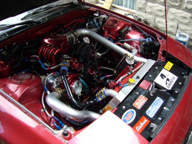
Leaving off from the last thread, we ended on a passenger side shot of the completed engine bay. Through the rest of last summer the car was tuned, driven, taken to the track and just plain enjoyed. However with it's new found power, the worn out suspension became even more obvious. During the winter while the car rested happily in the garage it was time to go shopping.
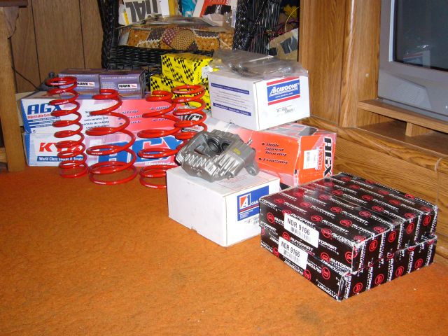
An order to Mazdatrix resulted in a wonderfully large box showing up at the door a week later. Contained within was a set of Racing Beat springs, KYB AGX shocks, new clutch slave and master cylinder, stainless brake and clutch lines, and a set of Hawk HPS brake pads. A trip to the local auto parts store to pick up a set of 4 piston front calipers and 5 lug rotors completed the pile. Always nice to have a stack of parts to stare at while watching TV in the cold of winter.
As soon as spring came, it was time to get right down to work on the car. After pushing it out of storage it was prepped to drive and then taken on a short journey to make sure everything was as it should be. Immediately after, the real work started. The short drive had reminded me of an annoyingly intermittent sticking front caliper. Additionally, the single piston brakes were becoming a safety hazard. They are simply not adequate to rein in 400 HP. This became obvious during some 1/4 mile runs, and even before that when tuning out at the airport. Something had to be done and a new set of single piston calipers would not do the job.
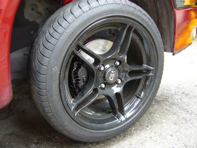
Everyone knows that a 5 lug swap gets you the 4 piston calipers, which is all fine and dandy if you have a set of gross stock wheels. But what if you already have an investment in a nice set of aftermarket wheels? I'm perfectly happy with the split 5 spoke CSA wheels I've had on this car for years and can't imagine a wheel style that fits the 2nd gen any more perfectly. Moving to a 5 lug setup would get me the big brakes, but mean I would also have to swap wheels. Unacceptable. Knowing that the spindle setup for both 4 and 5 lug are the same, I figured there would have to be a way to mount the 4 piston calipers on a 4 lug car with a minimum of fuss. As it turns out, the calipers bolt right on after you remove the bracket for the single piston unit.
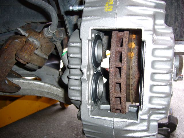
The calipers fit fine, but we all know the 4 lug rotor is much smaller then the 5 lug. Just putting on the 4 piston calipers is pointless as half the pad area is hanging off the rotor.
I figured it would be easy to redrill the 5 lug rotors to fit the 4 lug hub, and I was mostly correct. The 4 lug rotor was placed on top of the 5 lug rotor to decide where to place the new holes. As you can see, the center locating hole is the same on both rotors. This means the hub-centric rotor will stay centered on the hub even with a set of hand drilled holes.
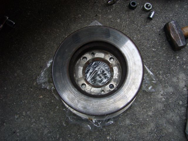
I drilled the holes out to 13MM, just a bit bigger then the factory holes. This allows a bit of wiggle room since when hand drilling, things can move a little bit. At this point the 5 lug rotor is now a hybrid 4/5 lug, and will fit either hub. You see this often in aftermarket brake kits. It thus mounted to the 4 lug hub without any drama.
It was time to bolt up the caliper, and it's here I ran into a small snag. It seems that Mazda decided to make the cast face of the 4 lug rotor a lot thicker then the 5 lug. Placing the redrilled 5 lug rotor onto the 4 lug hub made it seem as if it fits, but this is not so. Once the caliper was bolted in place, the back of the rotor scrapped the caliper. Confused, I measured the thickness front to back of both rotors. It turned out the same so that was not the cause. I then measured the thickness of the face of the hat on both rotors and found my issue. It seems the face of the 4 lug rotor is about 4MM thicker then the face of the 5 lug rotor. Thus, the 5 lug rotor sat further back off of the hub and smacked the caliper. To overcome this I stacked washers behind the rotor to move it back out to the center of the caliper. Below is a mockup of the brake setup using the washers as a spacer.
I then drew up a spacer in CAD and sent the drawing off to the local laser cutter to have some made in 4MM steel.
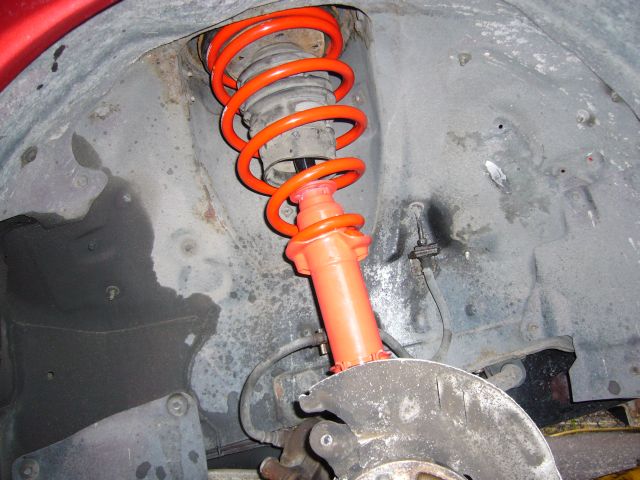
While the spacers were getting cut, I turned my attention to the suspension. A new set of KYB AGX shocks and RB springs were installed front and rear. I also replaced the supper strut mounts at the same time as the originals were 22 years old and well past their useful life.
No pictures of the rears as I only had the spring compressor for the weekend and ran into s small snag. The driver swapped out with no issues, but the passenger was another story. The lower strut mount (located on the control arm) was totally mangled due to a past "mechanic" over tightening the bolt. The mount was ballooned out, which also destroyed the bottom of the strut. Attempting to remove the bolt promptly snapped it, and the strut then had to be forcibly removed with a pry bar. The result was that a replacement mount was needed. Unfortunately the Mazda dealer could not get that bolt as the parts catalog showed NLA; No Longer Available. Luckily Joe of RPM Motorsports had a replacement on hand from a J-spec clip. A bit of heating and impacting removed the broken mount, then the new mount and strut was installed. For the record, the hex on these mounts is a weird sized metric...It doesn't exist. However a 1 1/8" deep well impact socket will fit it as long as the hex is undamaged.
A few days later the machine shop was finished with the 4 lug 4 piston spacers.
![]()
The inner radius of the spacer needed a bit of grinding to fit flush on the hub as the factory hub casting has a little bit of a taper to it. A few minutes with the grinding wheel and it fit perfectly. I anti-seized it up and then placed it on the hub.
![]()
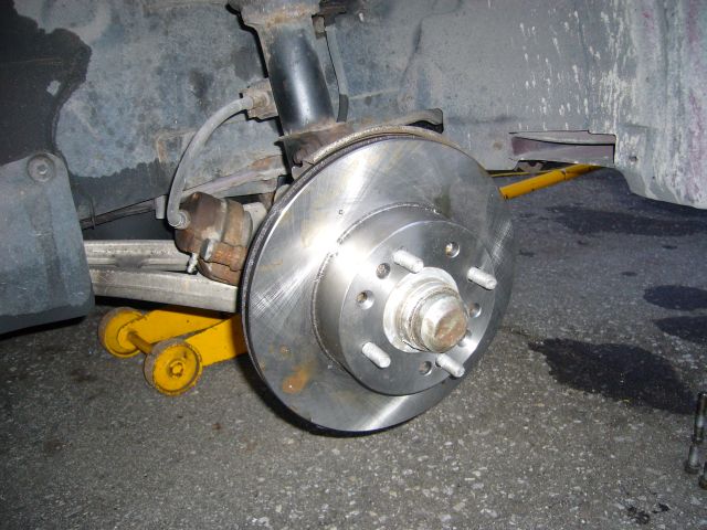
Next, the rotor was installed. Nothing annoys me more then rusted brake rotors so I sprayed the hat and outer edge with some VHT silver caliper enamel to help keep them looking fresh. You'll also notice that the stock dust shield was cut in order to fit the larger diameter rotors. I could have used the 5 lug shield, but this was far easier and will allow more cooling air to the rotors.
![]()
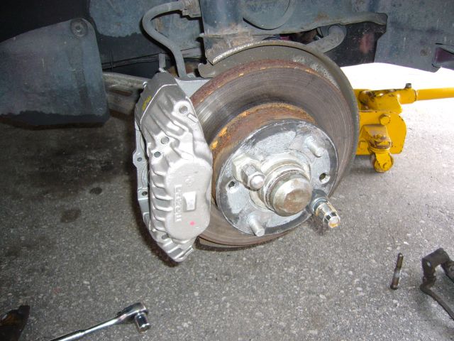
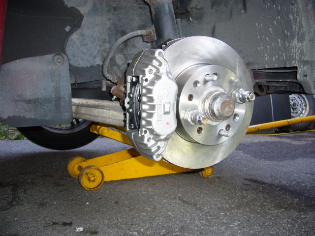
Finally the calipers were installed after being painted with VHT black caliper enamel. Funny, I purchase this paint constantly and have for years yet this is the first time I have ever used it on an actual brake caliper. The caliper bolted right up aside from one annoyance. For some odd reason my 4MM spacers moved the rotor closer to the outer side of the caliper then the inner. Functionally this is no problem, but it does look odd when the wheel is removed and you are looking directly at the end of the caliper. If you are going to have your own spacers cut, use steel closer to 3MM. The stainless DOT approved lines from Mazdatrix fit up fine. Note that they are the single piston lines.
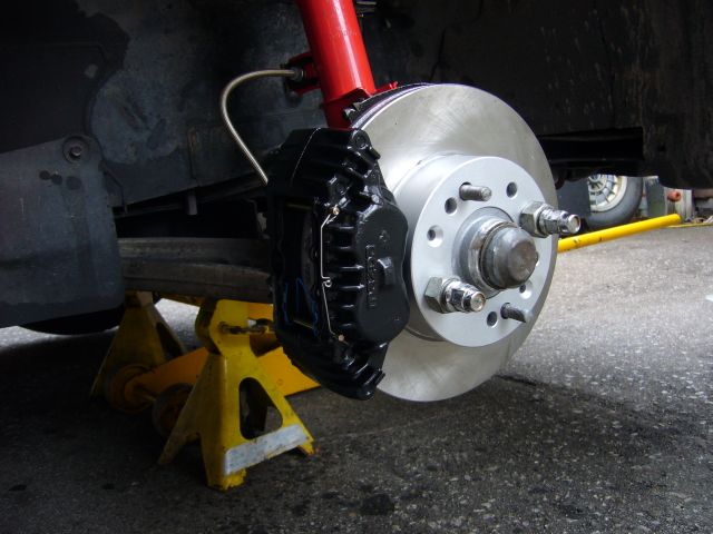
The complete 4 piston 4 lug setup. I wonder how many people would notice what's wrong with this picture?
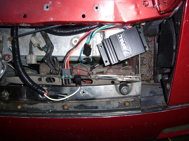
With the brakes complete it was time to fix another annoyance with the car; the e-fan. Controlling the e-fan relay with the Microtech works just fine, but the fan cycles on and off annoyingly. The temp of the car goes up, so the fan comes on. Then it cools back down and the fan shuts off. Rinse and repeat for as long as you are driving slowly. It got on my nerves and was nowhere near as transparent as the stock clutch fan. After reading about the SPAL FAN-PWM on the forums, I decided to give it a try.
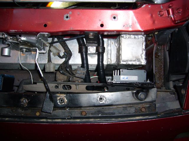
On a rainy Saturday afternoon I wired it into the car. I made a small mounting plate to located the FAN-PWM near the stock front relays.
I then modified my harness with the harnesses included with the FAN-PWM, tying into the stock engine coolant temp sensor with the white wire as per the instructions. The harness was then loomed up and secured into place.
The idea of this controller is that it turns your electric fan (on/off) into a clutch fan (continuously variable) by reading engine temperature and adjusting the fan speed to match. In theory it's a wonderful idea, but in practice I'm torn as to loving the unit, or hating it. There are problems with the unit's construction and design.
I applaud SPAL for trying to build a quality product by using WeatherPack connectors. However the connectors they used are clearly made in China and of inferior quality. The plastic feels weak and shows casting flash, and the silicone seals are poorly molded and very transparent.
The unit itself seems to mostly work as advertised. I have my fan set to low speed around 78C and high speed around 92 C. Thus at thermostat temp of about 84C it is at half speed. However this was very difficult to achieve. Because the circuit itself is poorly designed it was a real pain getting this thing to work. SPAL combined the signal and power ground in the circuit, something even a 1st year electrical engineering student knows not to do. The temp sensor input is also not isolated. This in combination with the ground setup means that a voltage offset can form when the fan draws high currents. The poor quality WeatherPack connector introduced a bit of resistance into the ground line, which totally messed up the voltage the unit was seeing from the temp sensor. This caused the unit to misread the temperature and be unsettable. It basically ran the fan high all the time. It was only after a week's worth of tech support emails to SPAL that I was told to cut the ground line off of the WeatherPack and ground directly to the chassis. Once I did, it behaved for the most part.
The other design issues are with the control algorithm. It's totally linear, which anyone versed in electronic control systems knows is almost never an appropriate method for a closed loop system. For example, if the fan is set to run half speed at 84 degrees and full speed at 94 degrees, it runs at 55% at 85C, 60% at 86C, 70% at 87C, etc. The issue is that this linear approach means the car can "stick" at a temperature. Even though the fan is running faster, there is more heat to remove so they cancel each other out. What's needed is a "gain" setting. The fan needs to overshoot the target speed for a little bit. Using the example above, the fan should run at 80% at 87C until the temp drops to 86C and then resume it's normal 60%. The higher off the target temp of the vehicle, the faster the fan should run to bring it down. That's now closed loop control is properly done in this case.
Additionally, setting the unit is confusing. If you accidentally set the low speed and high speed temps too close, the fan simply won't run. This is not an acceptable fail safe. The fan should either run at high speed until the situation is corrected, or a medium like 80%.
Those faults aside, the unit does seem to be working for me now. After tweaking the high and low settings for a week or so I've got the fan adjusted properly. Another bit of good news is that in speaking with the SPAL engineers, they have told me the new version of the circuit fixes the ground issue. They didn't isolate the input, nor did they implement a gain control, but they did add a signal ground. That should go a long way to solving the problem.
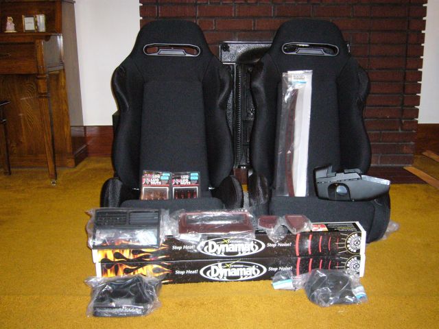
With the fan nonsense behind me it was time to turn my attention to the interior. The existing interior of the car, aside from being half ripped out, was in terrible shape. The maroon carpet had faded to green, the seats were covered in stains of unknown biological origin, and most of the plastic had long since cracked. Again, it was time to spend some money at Mazdatrix. I ordered much of the commonly broken trim: idiot light surround, demister grills, front defroster grills, shifter surround and boot, steering column cover, heater vents and rubber shifter boots. From Jim's Speed came a few rolls of Dynamat. As it turns out, I would need a LOT more Dynamat. The seats are just some made in China sport seats that I literally purchased out of the back of a van in a Petro Canada parking lot in Scarborough (Toronto's ghetto). The quality and comfort of these seats surprised me. Will they last 20 years? Probably not. But for the price and the 5 years I will get out of them I'm not worried. Also I grabbed a set of red anodized lug nuts, just because.
Not shown in the picture is the Auto Custom Carpets carpet set, purchased from Black Dragon. We'll talk about that later.